RUGGEDCOM RX1501
Installation Guide
Chapter 3
Communication Ports
Copper Ethernet Ports 19
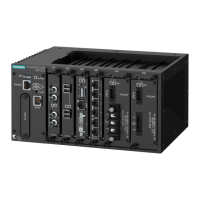
Figure 23: 4 x 4-Pin 10/100TX M12 D-Coded Ports
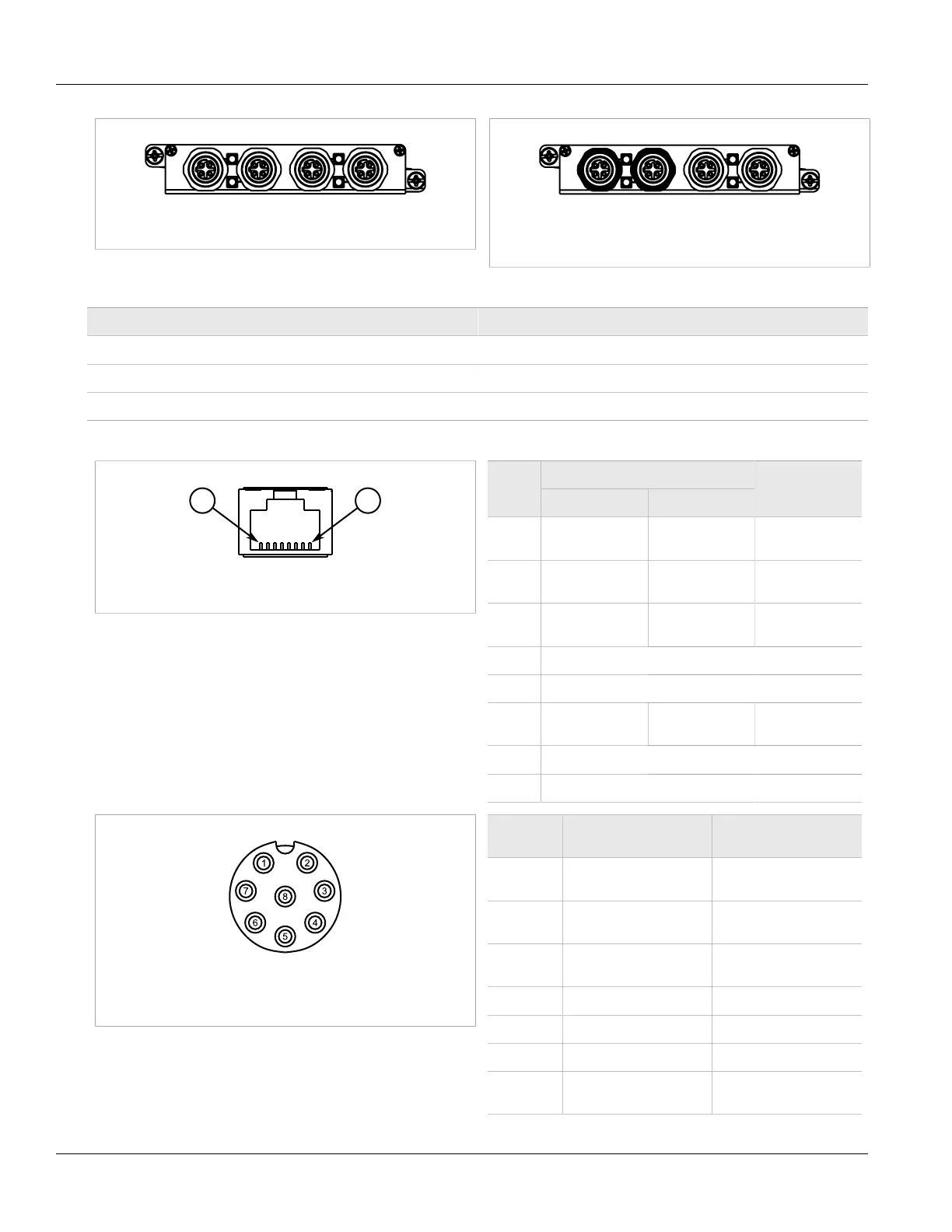
Figure 24: 4 x 4-Pin 10/100TX with M12 D-Coded
Bypass and Non-Bypass Ports
Each port features an LED that indicates the state of the port.
State Description
Green (Solid) Link established
Green (Blinking) Activity
Off No link detected
The following are the pin-out descriptions for the RJ45 and M12 connectors:
Figure 25: RJ45 Ethernet Port Pin Configuration
Name
Pin
10/100Base-TX 1000Base-TX
Description
1 RX+ BI_DB+ Receive Data+
or Bi-Directional
2 RX- BI_DB- Receive Data-
or Bi-Directional
3 TX+ BI_DA+ Transmit Data+
or Bi-Directional
4 Reserved (Do Not Connect)
5 Reserved (Do Not Connect)
6 TX- BI_DA- Transmit Data-
or Bi-Directional
7 Reserved (Do Not Connect)
8 Reserved (Do Not Connect)
Figure 26: 8-Pin M12 A-Coded Ethernet Port Pin
Configuration
Pin 10/100Base-Tx Signal
10/100/1000Base-
Tx Signal
1 Reserved (Do
Not Connect)
a
C+
2 Reserved (Do
Not Connect)
a
D+
3 Reserved (Do
Not Connect)
a
D-
4 TX- A-
5 RX+ B+
6 TX+ A+
7 Reserved (Do
Not Connect)
a
C-