RUGGEDCOM RX1501
Installation Guide
Chapter 3
Communication Ports
Cellular Modem Modules 25
State Description
Green Activity detected
Off No activity
For specifications on serial ports, refer to Section 4.3, “Copper Serial Port Specifications”.
For information about how to connect devices configured to run in RS485 mode, refer to Section 3.10,
“Connecting Multiple RS485 Devices”.
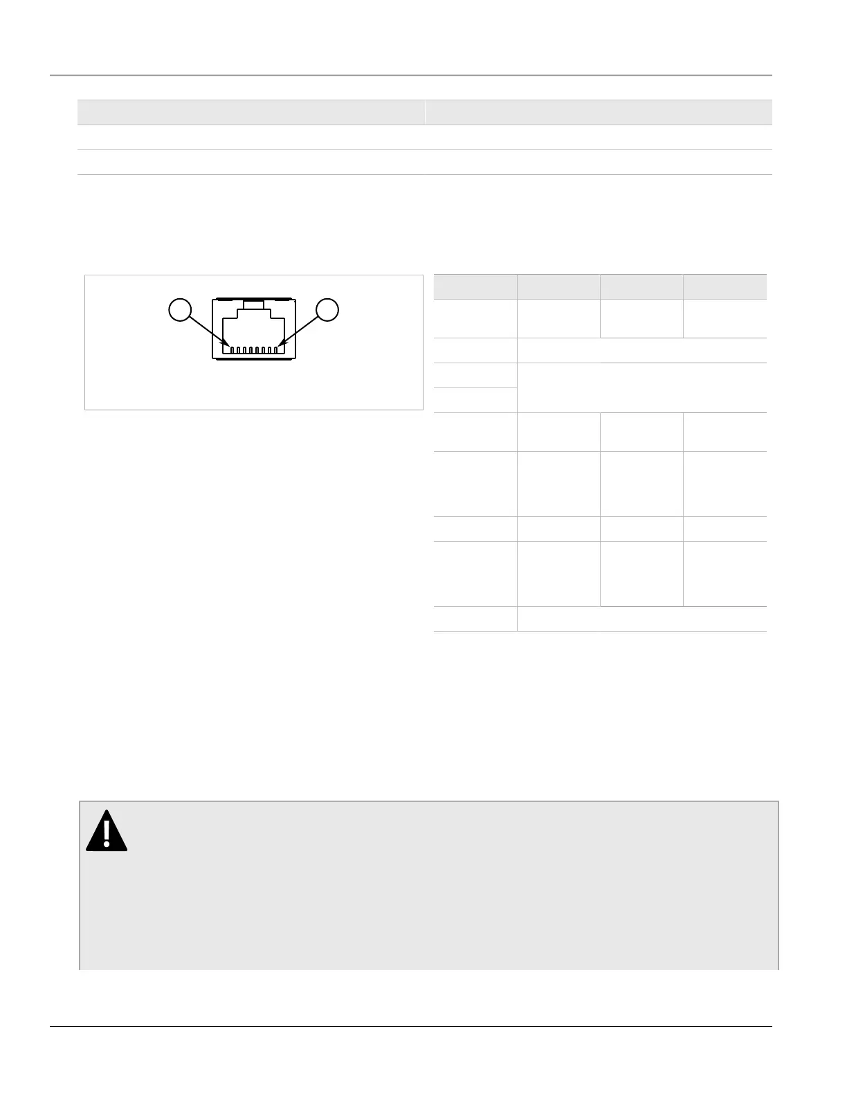
The following are the pin-outs for the RJ45 connectors:
Figure 42: Serial RJ45 Port
Pin RS232 Mode RS485 Mode RS422 Mode
1 RX- (Receive
Negative)
2 Reserved (Do Not Connect)
3
4
Common (Isolated) Ground
5 RX (Receive) RX+ (Receive
Negative)
6 TX (Transmit) TX/RX+
(Transmit/
Receive
Positive)
TX+ (Transmit
Positive)
7 Note
b
8 Note
b
TX/RX-
(Transmit/
Receive
Negative)
TX- (Transmit
Negative)
Shield Chassis Ground
b
Pins 7 and 8 are connected together internally.
Section 3.6
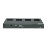
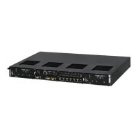
Cellular Modem Modules
The RX1501 supports the following cellular modem line modules for operation on GSM, EDGE, HSPA+, or CDMA
networks:
DANGER!
Radio interference hazard – risk of death, serious personal injury or equipment damage. Do not
operate the cellular modem in the following areas:
• Areas where explosives are actively used
• In explosive atmospheres, such as refueling stations, fuel depots, chemical plants, underground
mining operations, etc.
• Near medical or life support equipment or devices
• In any aircraft, whether in flight or on the ground (unless permitted by the aircraft operator)