RUGGEDCOM RX1501
Installation Guide
Chapter 3
Communication Ports
SFP Optic Ethernet Ports 21
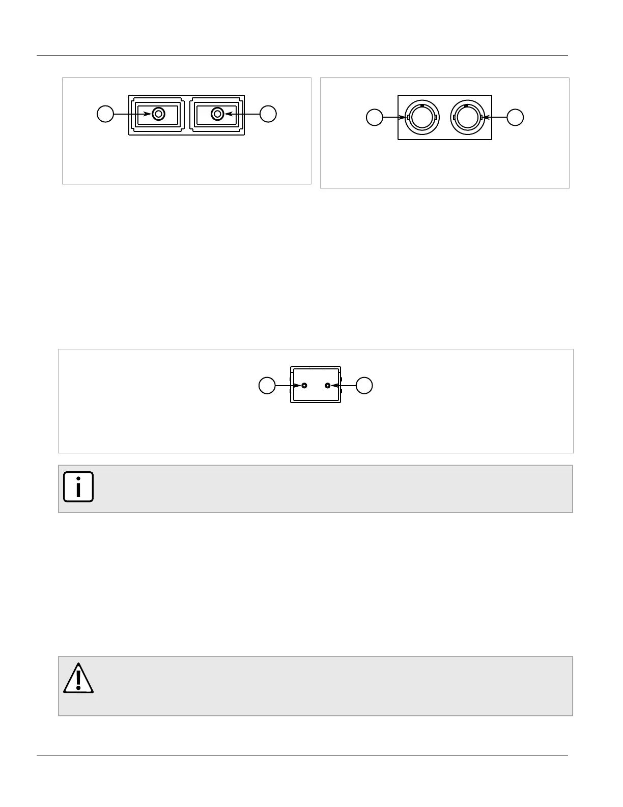
Figure 31: SC Port
1. Tx Connector 2. Rx Connector
Figure 32: ST Port
1. Tx Connector 2. Rx Connector
For specifications on the available fiber optic Ethernet ports, refer to Section 4.5, “Fiber Optic Ethernet Port
Specifications”.
Section 3.3
SFP Optic Ethernet Ports
SFP (Small Form-Factor Pluggable) optic Ethernet ports are available with LC (Lucent Connector) connectors.
Make sure the Transmit (Tx) and Receive (Rx) connections of each port are properly connected and matched to
establish a proper link.
Figure 33: LC Port
1. Tx Connector 2. Rx Connector
NOTE
SFP modules, as well as their optical ports, can be safely inserted and removed while the chassis is
powered and operating.
The following sections describe how to install and remove SFP optical ports:
• Section 3.3.1, “Installing an SFP Optical Port”
• Section 3.3.2, “Removing an SFP Optical Port”
Section 3.3.1
Installing an SFP Optical Port
To install an SFP optical port, do the following:
CAUTION!
Electrical hazard – risk of damage to equipment. Use only components certified by Siemens with
RUGGEDCOM products. Damage to the module and device may occur if compatibility and reliability
have not been properly assessed.
 Loading...