Home
Siemens
Industrial PC
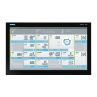
SIMATIC IPC277G
Siemens SIMATIC IPC277G User Manual
4
of 1
of 1 rating
123 pages
Give review
Manual
Specs
To Next Page
To Next Page
To Previous Page
To Previous Page
Loading...
Markings an
d symbols
B.5
Inte
rfaces
SIMAT
IC IPC277G
Operating Inst
ructions
,
08/2021
,
A5E
500599
56
-
AA
109
B.5
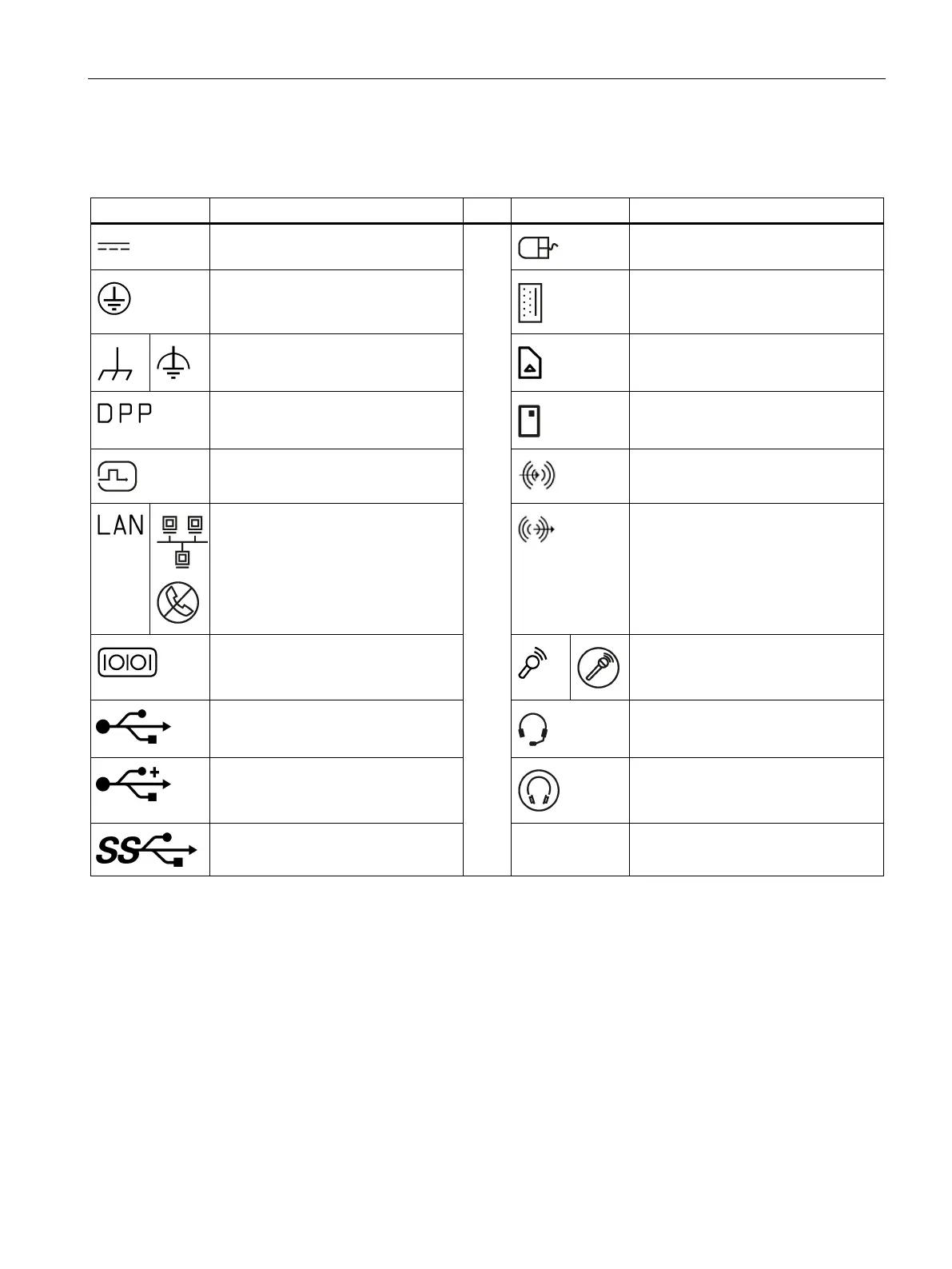
Interfaces
Symbol
Meaning
Symbol
Meaning
Conne
ction to
the
pow
er su
pply
PS/2
mou
se inte
rface
Prote
ctive conductor
term
inal
PS/2 k
eyboar
d
-
interfa
ce
Conne
ction f
or f
unction
al ear
thing
(equipo
tential bonding line)
Multimedia Car
d Reade
r
DisplayPo
rt interf
ace
Smar
t Card
Re
ader
DVI
-
D in
terface
Lin
e In
LAN in
terface,
not approved fo
r
connecti
ng W
AN or
tele
p
hone
Line Ou
t
Serial p
ort
Micro
phone
input
USB port
Universa
l Audio Jack
USB 2.0 hi
gh
-
speed port
Headphone output
USB 3.0 sup
er
-
speed port
108
110
Table of Contents
Preface
3
Table of Contents
5
Overview
8
Product Description
8
Configuration Plan
9
Structure of the Devices
10
7" and 10" Multi-Touch Devices
10
12", 15", 19", 22" and 24" Multi-Touch Devices
11
7" and 10" Devices - Interfaces and Operator Controls
12
12", 15", 19", 22" and 24" Devices - Interfaces and Operator Controls
12
Accessories
13
Safety Instructions
15
General Safety Instructions
15
Security Information
17
Data Protection
18
Disclaimer for Third-Party Software Updates
18
Notes on Use
18
Installing and Connecting the Device
19
Preparing for Installation
19
Checking the Delivery Package
19
Identification Data of the Device
20
Permitted Mounting Positions
22
Preparing the Mounting Cutout
23
Mounting the Device
24
Mounting Instructions
24
Secure with Mounting Clips
26
Fastening a Device Using a VESA Adapter
29
Connecting the Device
31
Notes on Connecting
31
Connecting the Protective Earth
33
Connecting the Power Supply to the 7" and 10" Devices
34
Connecting the Power Supply to the 12", 15", 19", 22" and 24" Devices
35
Installing Ethernet Connector Strain Relief
37
Installing the Cable Strain Relief
38
Securing Cables
38
Securing Cables for Use in Hazardous Areas
38
Connect Device to Networks
39
Commissioning the Device and Device Functions
40
General Information on Commissioning
40
Switching the Device On/Off
40
Advanced Device Functions
42
Monitoring Functions
42
Overview of the Monitoring Functions
42
Temperature Monitoring/Display
42
Watchdog (WD)
43
Battery Monitoring
44
Buffer Memory NVRAM
44
Operating the Device
45
Operator Input Options
45
IPC Driver and Tools
46
Operating a Device with Capacitive Multi-Touch Screen
46
Expanding and Assigning Parameters to the Device
49
Open the Device
49
Installing the M.2 Module
51
Installing and Removing M.2 Nvme/ SATA SSD
55
Maintaining and Repairing the Device
57
Maintenance Intervals
57
Repair Information
57
Cleaning the Device Front
58
Installing and Removing Hardware
60
Replacing the Backup Battery
60
Replacing the Memory Module
62
Reinstalling the Operating System
66
Installing the Drivers and Software
66
Recycling and Disposal
69
Technical Specifications
70
Certificates and Approvals
70
Directives and Declarations
73
Electromagnetic Compatibility, Industrial and Residential Areas
73
Rohs Directive
74
ESD Guideline
74
Dimension Drawings
76
Dimension Drawing of 7" Device
76
Dimension Drawing of 10" Device
77
Dimension Drawing of 12" Device
78
Dimension Drawing of 15" Device
79
Dimension Drawing of 19" Device
80
Dimension Drawing of 22" Device
81
Dimension Drawing of 24" Device
82
Technical Data
83
General Technical Specifications
83
Ambient Conditions
87
Power Demand of the Components
89
Power Supply 7" and 10" Device
89
Power Supply 12", 15", 19", 22" and 24" Device
90
Hardware Descriptions
91
Technical Features of the Motherboard
91
External Interfaces
91
Overview of External Interfaces
91
USB 3.1 Port
91
DC in Connector
92
Ethernet Port
92
Displayport
93
Serial Interface
94
Internal Interfaces
95
Overview of Internal Interfaces
95
USB 2.0 Pin Header
95
Interface
95
LVDS Interface
97
Backlight Interface
98
System Resources
98
Input/Output Address Areas
99
Overview of the Internal Module Registers
99
Watchdog Control Register
99
Watchdog Counter Register
99
Watchdog State Register
100
Battery Status Register
100
NVRAM Address Register
100
BIOS Description
101
Overview
101
BIOS Update
102
Alarm, Error and System Messages
103
Technical Support
104
Service and Support
104
Troubleshooting
105
Notes on the Use of Third-Party Modules
106
Markings and Symbols
107
Overview
107
Safety
107
Operator Controls
107
Certificates, Approvals and Markings
108
Interfaces
109
List of Abbreviations
110
Glossary
113
Index
121
4
Based on 1 rating
Ask a question
Give review
Questions and Answers:
Need help?
Do you have a question about the Siemens SIMATIC IPC277G and is the answer not in the manual?
Ask a question
Siemens SIMATIC IPC277G Specifications
General
Brand
Siemens
Model
SIMATIC IPC277G
Category
Industrial PC
Language
English
Related product manuals
Siemens SIMATIC IPC277E
158 pages
Siemens simatic ipc227e
156 pages
Siemens SIMATIC IPC227G
115 pages
Siemens SIMATIC IPC827D
186 pages
Siemens SIMATIC IPC427D
200 pages
Siemens SIMATIC IPC677D
196 pages
Siemens SIMATIC IPC547J
198 pages
Siemens SIMATIC IPC477E
188 pages
Siemens SIMATIC IPC847D
222 pages
Siemens SIMATIC IPC627E
164 pages
Siemens Simatic IPC647C
246 pages
Siemens SIMATIC IPC647E
200 pages

 Loading...