Description of system components
8.5 Current / voltage measuring modules (UM, UM+) for the SIMOCODE pro V High Performance device series
SIMOCODE pro
136 System Manual, 05/2019, A5E40507475002A/RS-AD/004
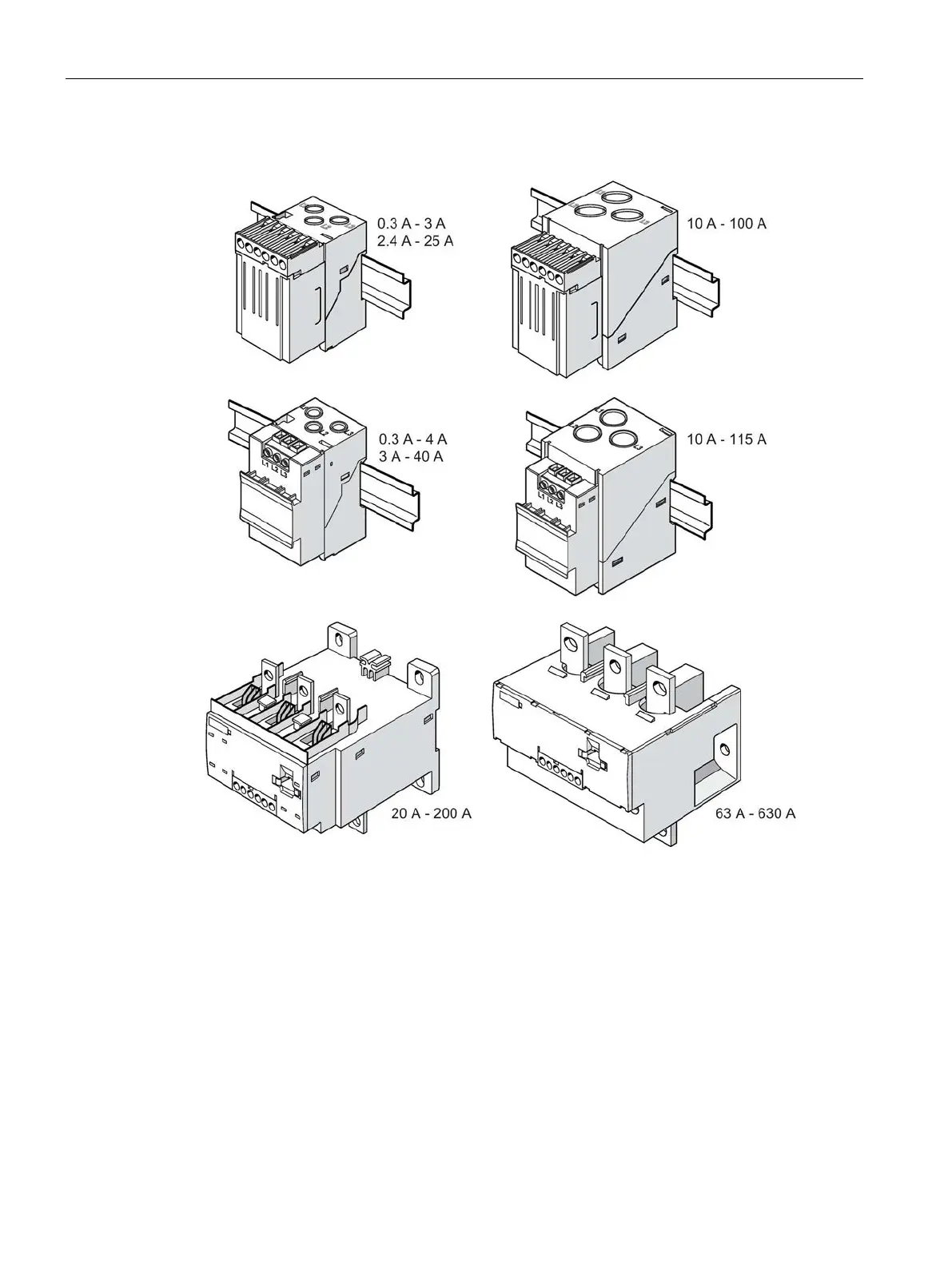
The diagram below shows the various current / voltage measuring modules:
Figure 8-31 Variants of current / voltage measuring modules
Wiring:
The current / voltage measuring modules are connected to the basic unit via a connecting
cable, which also supplies the power.
For the purpose of calculating or monitoring power-related measured values, current /
voltage measuring modules are equipped with additional, removable terminals to which the
voltages of all three phases of the main circuit are connected. An additional 3-core cable can
be used, for example, to connect the main circuit directly from the bus connections of the
current / voltage measuring module with the connection terminals of the voltage measuring
module.

 Loading...


