Mounting, wiring, connecting, system interfaces, configuration guidelines
12.2 Wiring, connecting
SIMOCODE pro
System Manual, 05/2019, A5E40507475002A/RS-AD/004
223
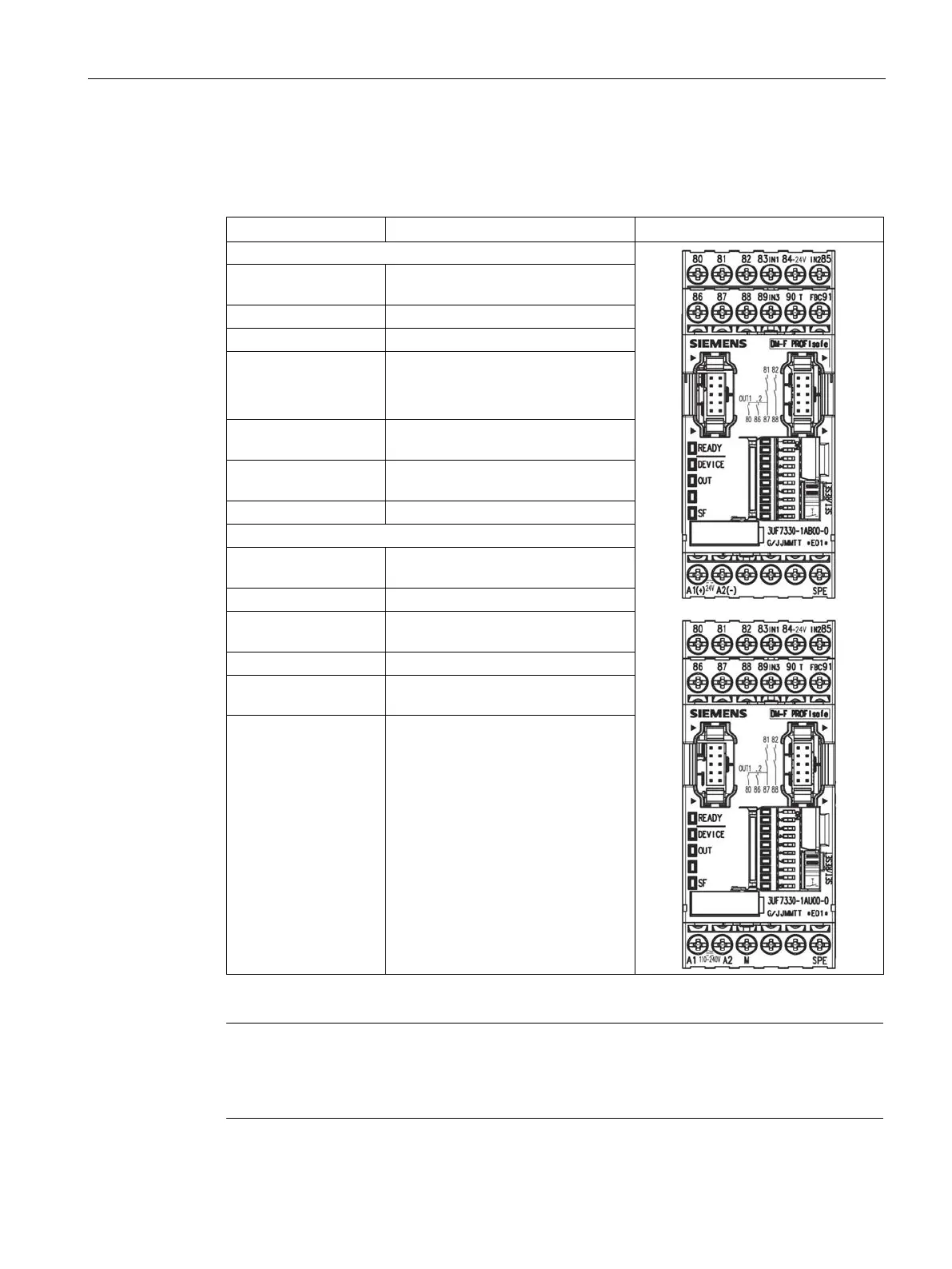
Terminal assignment for digital module DM-F PROFIsafe
Table 12- 19 Terminal assignment of the removable terminals of the digital module DM-F PROFIsafe,
24 V DC version and 110 to 240 V UC version.
80, 86 Digital module, relay outputs 1 (80)
Relay enabling circuit 1, NO
82, 88 Relay enabling circuit 2, NO
83 (IN1)
85 (IN2)
Digital module, inputs 1, 2, 3
84 Power supply, diigital module, inputs
90 (T) Feedback circuit supply (FBC)
A1 (+) Power supply connection 110 to
M Ground (reference potential inputs,
T3 Supply for sensor inputs
SPE
1)
System shielding
1)
pro via terminal SPE with the maximum possible cross-section and
with as short a cable as possible to the functional ground of the control cabinet,
e.g. to the grounded mounting plate of the control cabinet.

 Loading...


