EasyManuals Logo

Siemens SINAMICS G120C Getting Started

Siemens SINAMICS G120C
68 pages
To Next Page IconTo Next Page
To Previous Page IconTo Previous Page
Page #42 background imageLoading...
Page #42 background image
Commissioning
4.2 Commissioning with BOP-2 operator panel
SINAMICS G120C converter
42 Getting Started, 04/2014, FW V4.7, A5E34264105B AA
4.2.3.4
Parameter list
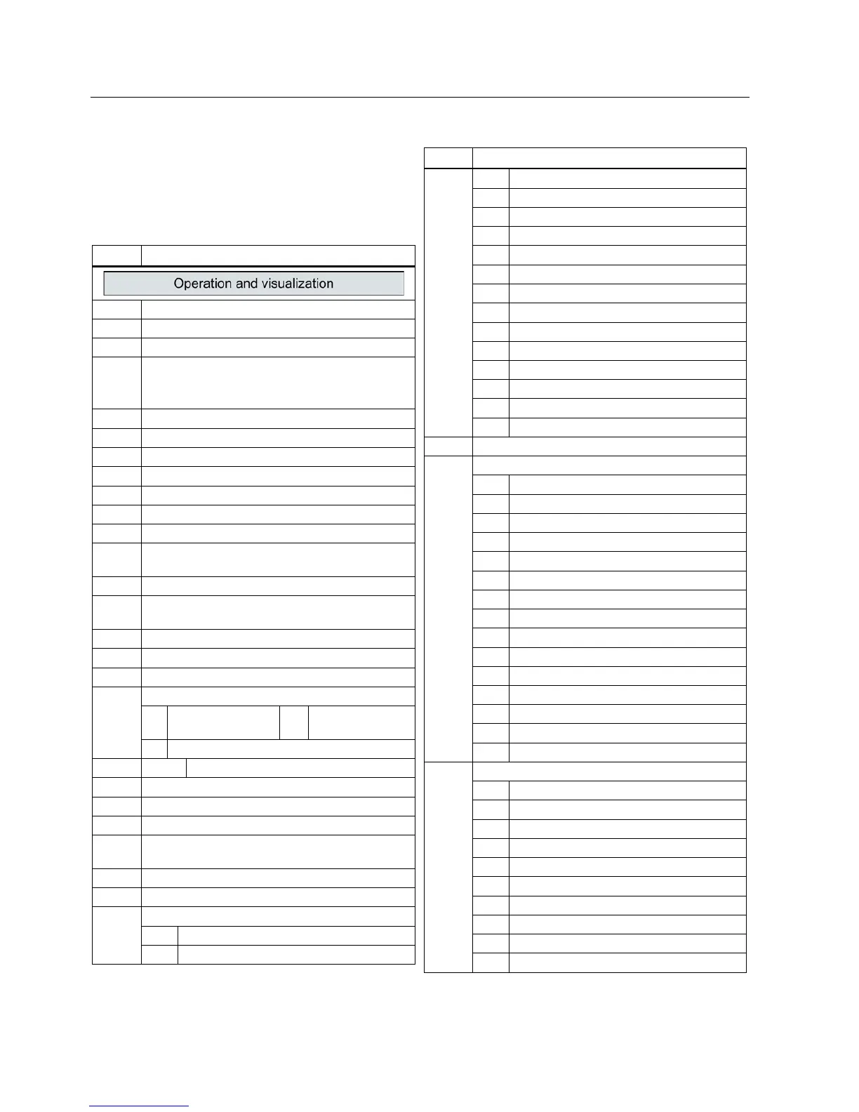
The following list contains the basic parameter
information with access level 13. The complete
parameter list is provided in the list manual, see
Product support (Page 65).
No.
Description
r0002
Drive operating display
p0003
Access level
p0010
Drive, commissioning parameter filter
p0015 Macro drive unit
See also Default settings of the terminals
(Page 25)
r0018
Control Unit firmware version
r0020
Speed setpoint smoothed [100 % p2000]
r0021 CO: Actual speed smoothed [100 % p2000]
r0022
Speed actual value rpm smoothed [rpm]
r0024
Output frequency smoothed [100 % p2000]
r0025
CO: Output voltage smoothed [100 % p2001]
r0026
CO: DC link voltage smoothed [100 % p2001]
r0027 CO: Absolute actual current smoothed
[100 % p2002]
r0031
Actual torque smoothed [100 % p2003]
r0032 CO: Active power actual value smoothed
[100 % r2004]
r0034
Motor utilization [100 100%]
r0035
CO: Motor temperature [100°C ≙ p2006]
r0036
CO: Power unit overload I
2
t [100 100%]
r0039
Energy consumption [kWh]
[0] Energy balance
(total)
[1] Energy drawn
[2]
Energy fed back
p0040
0 → 1
Reset the energy consumption display
r0041
Energy usage saved/energy saved
p0045
Smoothing time constant, display values [ms]
r0046
CO/BO: Missing enable signals
r0047 Motor data identification routine and speed
controller optimization
r0050 CO/BO: Command Data Set CDS effective
r0051
CO/BO: Drive Data Set DDS effective
r0052
CO/BO: Status word 1
.00
Ready to start
.01
Ready
No.
Description
.02
Operation enabled
.03
Fault active
.04
Coast down active (OFF2)
.05
Quick stop active (OFF3)
.06
Closing lockout active
.07
Alarm active
.08
Deviation, setpoint/actual speed
.09
Control requested
.10
Maximum speed reached
.11
I,M,P limit reached
.12
Motor holding brake open
.13
Alarm overtemperature motor
.14
Motor rotates forwards
.15
Alarm inverter overload
r0053
CO/BO: Status word 2
r0054
CO/BO: Control word 1
.00 ON/OFF1
.01
OFF2
.02 OFF3
.03
Enable ramp-function generator
.04
Enable ramp-function generator
.05
Continue ramp-function generator
.06
Enable speed setpoint
.07
Acknowledge fault
.08
Jog bit 0
.09
Jog bit 1
.10
Master control by PLC
.11
Direction reversal (setpoint)
.13
Motorized potentiometer, raise
.14
Motorized potentiometer, lower
.15
CDS bit 0
r0055
CO/BO: Supplementary control word
.00
Fixed setpoint, bit 0
.01
Fixed setpoint, bit 1
.02
Fixed setpoint, bit 2
.03
Fixed setpoint, bit 3
.04
DDS selection, bit 0
.05 DDS selection, bit 1
.08
Technology controller enable
.09
DC braking enable
.11
Droop enable
.12
Closed-loop torque control active

Other manuals for Siemens SINAMICS G120C

Questions and Answers:

Question and Answer IconNeed help?

Do you have a question about the Siemens SINAMICS G120C and is the answer not in the manual?

Siemens SINAMICS G120C Specifications

General IconGeneral
Communication InterfacesPROFINET, PROFIBUS, USS, Modbus RTU
Protection ClassIP20
Ambient Temperature-10°C to +50°C
Storage Temperature-40°C to +70°C
Power Range0.55 kW to 132 kW
Voltage Range380 V to 480 V
Output Voltage0 V to Supply Voltage
Frequency Range0 Hz to rated output frequency
Control ModesVector control with encoder
ProtectionOverload, overvoltage, undervoltage, short circuit, ground fault
Relative Humidity5% to 95%, non-condensing
AltitudeUp to 2000 m without derating

Related product manuals