SIPART DR19
76 C73000-B7474-C140-06
Configuring Quick Reference
3.5 CAE3 - UNI Input AI3
To select measuring ranges for the UNI (universal) input AI3 and trim if necessary.
The UNI input must be allocated to AI3 by setting S9>3. The input signal is
selected by S10.
• The selected measuring range is passed to the controller, where it is accessible
as AI3A as a standardized numerical value in the range 0 to 1. This variable can
be configured as required within the controller using configuring switches S15
to S20.
• The measuring range of the UNI input is set using the parameters MA3, ME3,
MP3. The display range of the PV-X digital indicator is set independently of the
above using the Offline Parameters dA, dE, dP.
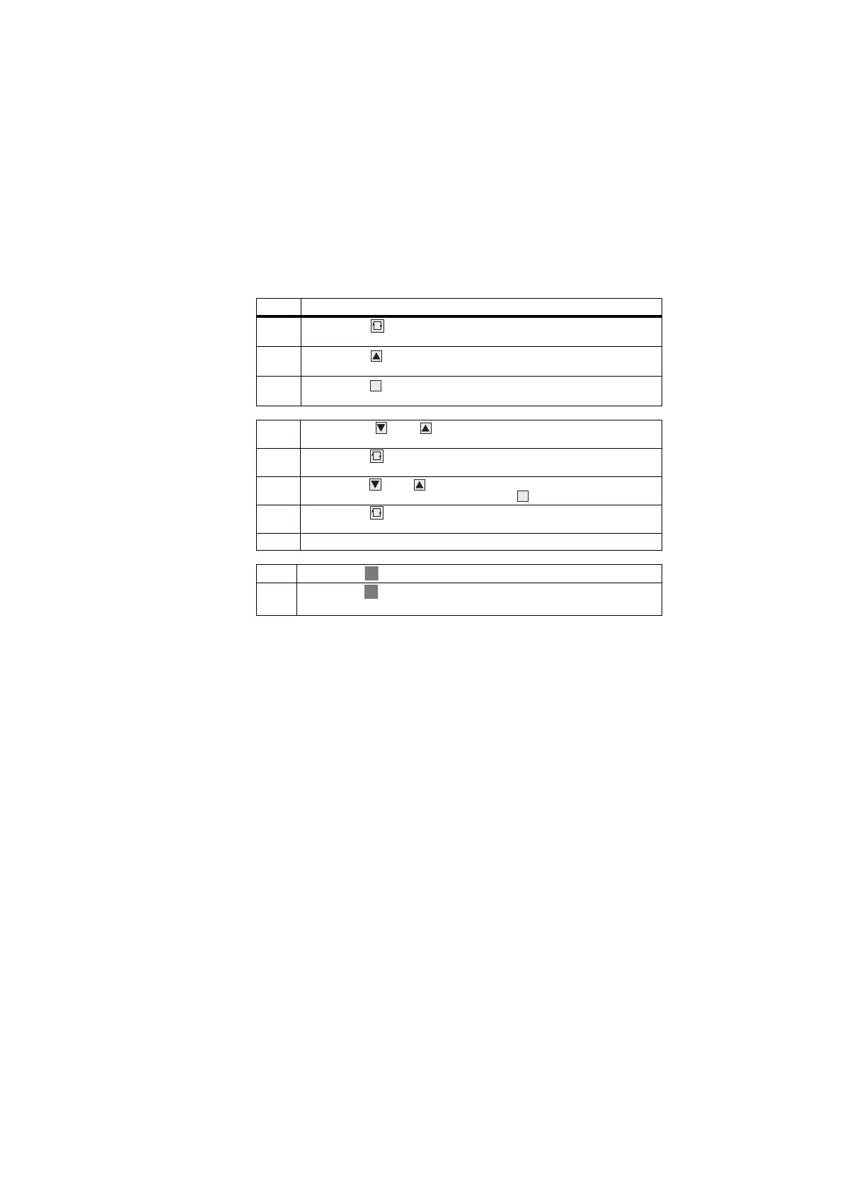
Step Procedure
1 Press button (6) about 5 sec until "PS" flashes. Release button -
"onPA" (selection level) displayed. Blocked if digital signal bLPS=1.
2 Press button (8) several times until "CAE1" is displayed (selection
level). Blocked if configuring switch S9<4.
3 Press button (9) about 3 sec until digital indicator SP-W (2) flashes
(configuring level). Controller now blocked and last value of y retained.
4 Using buttons (7) or (8). Select parameter names in the SP-W (2)
digital indicator.
5 Press button (6) once, indicator PV-X (1) flashes, input field is
switched over.
6 Using button (7) or (8). Modify the parameter value in the PV-X (1)
indicator, or invoke a function using button (9).
7 Press button (6) once, indicator SP-W (2) flashes, input field is
switched back.
8 Repeat steps 4 to 7 until all desired parameters are set.
9 Press button (13) once (selection level).
10 Press button (13) once (process control level). Controller is in manual
mode.
Purpose
Require-
ments
Mode of oper-
ation of UNI
input
Access to
the CAE3
function
et module
parameters
Exit to pro-
cess control
level
 Loading...


