Description, device design, dimension drawing
2.2 Connections and terminal designation
SITOP PSU100S
10 Operating Instructions, 02.2013, C98130-A7589-A1-3-7629
2.2 Connections and terminal designation
The line input terminals ① can be used to establish the connection to supply voltage. The
output terminals
② are used to connect to the loads to be supplied (see also Section
Installation (Page 35)).
The ope
rating state of the device can be processed via the signaling contact
③ (function
and contact rating, see Chapter Status displays and signaling (Page 12)).
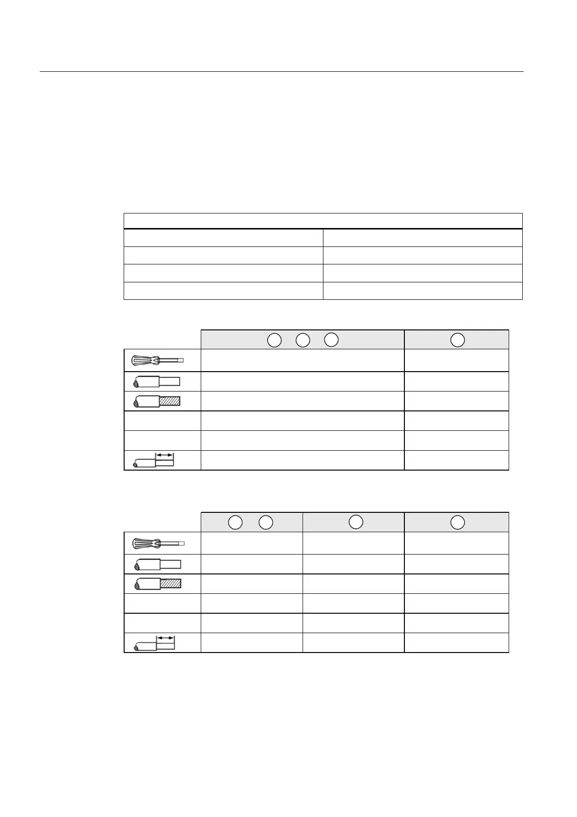
Connections and terminal designations
① Line input L1, N, PE
One screw terminal each
② Output +
2 screw terminals
② Output –
2 screw terminals
③ signal 13, 14
One screw terminal each
$:*
1P
6=6[3=3+
[PP
[PP
1P
PP
6=6[3=3+
PD[ෘPP
1P
Figure 2-2 Terminal data for 6EP1332-2BA20, 6EP1333-2BA20, 6EP1334-2BA20, 6EP1322-
2BA00, 6EP1323-2BA00
$:*
1P
6=6[3=3+
6=6[
6=6[3=3+
PD[ෘPP
[PP
[PP
[PP
[PP
1P
1P 1P
PP PP
Figure 2-3 Terminal data for 6EP1336-2BA10

 Loading...