HRX-OM-K003
Chapter 3 Transporting and Installation
3.3 Procedure for Installation HRW Series
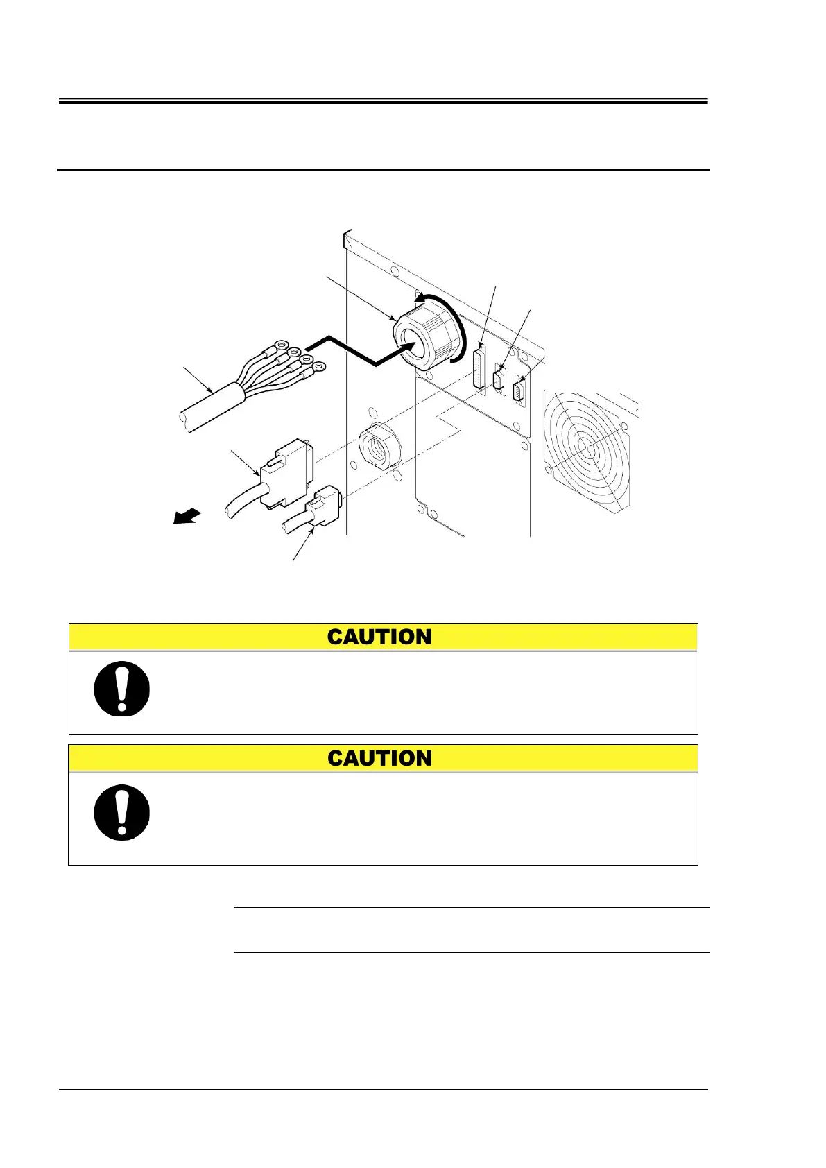
5. Loosen the cap and insert the power cable from the power cable access.
6. Connect the communication cables with P1 and P2.
[Tips]
See “Table 3-1 Power Cable and Main Breaker (This System)” on page 3-7
for the recommended cable size and crimp contact.
Figure 3-7 Power Cable Insertion and Communication Cable Connection
Correct phase rotation is required when attach the power cable to the
breaker terminal.
Do not drop a screw or washer in the electrical unit when attaching the
breaker cover and terminal.
Do not leave it in the unit if dropped in. Potential failure may occur if
the power is turned ON without removing it.
Serial RS-485 communication cable
P3 (D-sub 9P male)
Not used.
(Only for maintenance)

 Loading...