HEC-OM-O018-A
Chapter 5 Operation
5.1 Operation of Controller
5-13
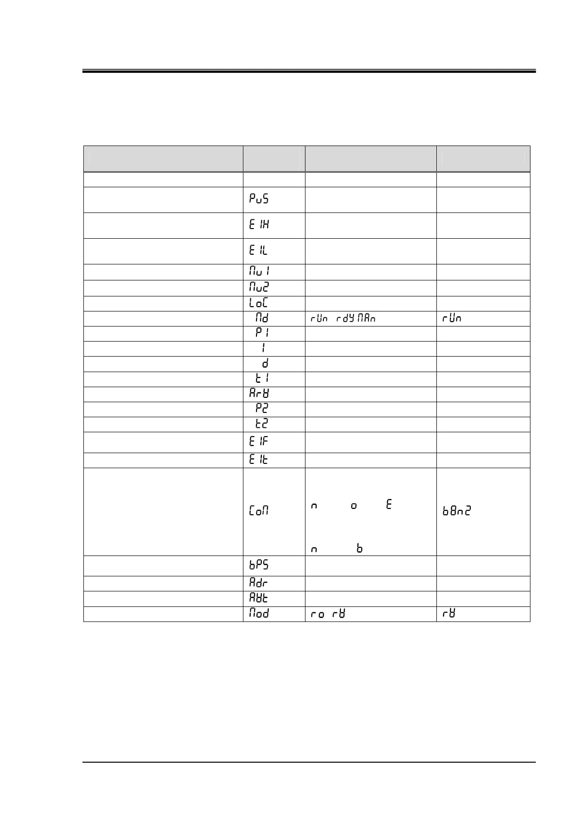
5.1.12 Initial Value and Setting Range for Each Mode
Table 5-2 Initial value and setting range for each mode
Description
Mode
indicator
Setting range Initial value
Setting of target temp. - 0.0 to 60.0 25.0
Offset setting
-1.0 to 1.0
According to the
Inspection Record
High temperature limit range
setting
0.0 to 10.0 1.5
Low temperature limit range
setting
0.0 to 10.0 1.5
Heating output indicator
− −
Cooling output indicator
− −
Key lock setting
0 to 3 0
Control mode setting
, ( , )
Heating Proportional Band Setting
0.1 to 200.0%
4.0
Integral Time Setting
0 to 3600
50
Derivative Time Setting
0 to 3600
0
Heating Proportional Cycle Setting
1 to 120
2
ARW setting
0.0 to 100.0
100.0
Cooling Proportional Band Setting
0.00 to 10.00
0.50
Cooling Proportional Cycle Setting
1 to 120
2
Event output function setting
1
st
digit: 0 to 8
2
nd
digit: 0 to 3
01
Event output delay timer setting
0 to 9999
0
Communication parameter setting
1
st
digit: Stop bit length function
1: 1 bit, 2: 2 bit
2
nd
digit: Parity check function
: None, : Odd, : Even
3
rd
digit: Data length selection
7: 7 bit, 8: 8 bit
4
th
digit: BCC check function
:Disable, : Enable
Communication speed setting
1.2 to 19.2
(1200bps to 19200bps)
9.6
Communication address setting
1 to 99
1
Response delay time setting
0 to 250 ms
0 ms
Communication-mode setting
,
 Loading...