- 52 -
10.2 When supplying power for the first time
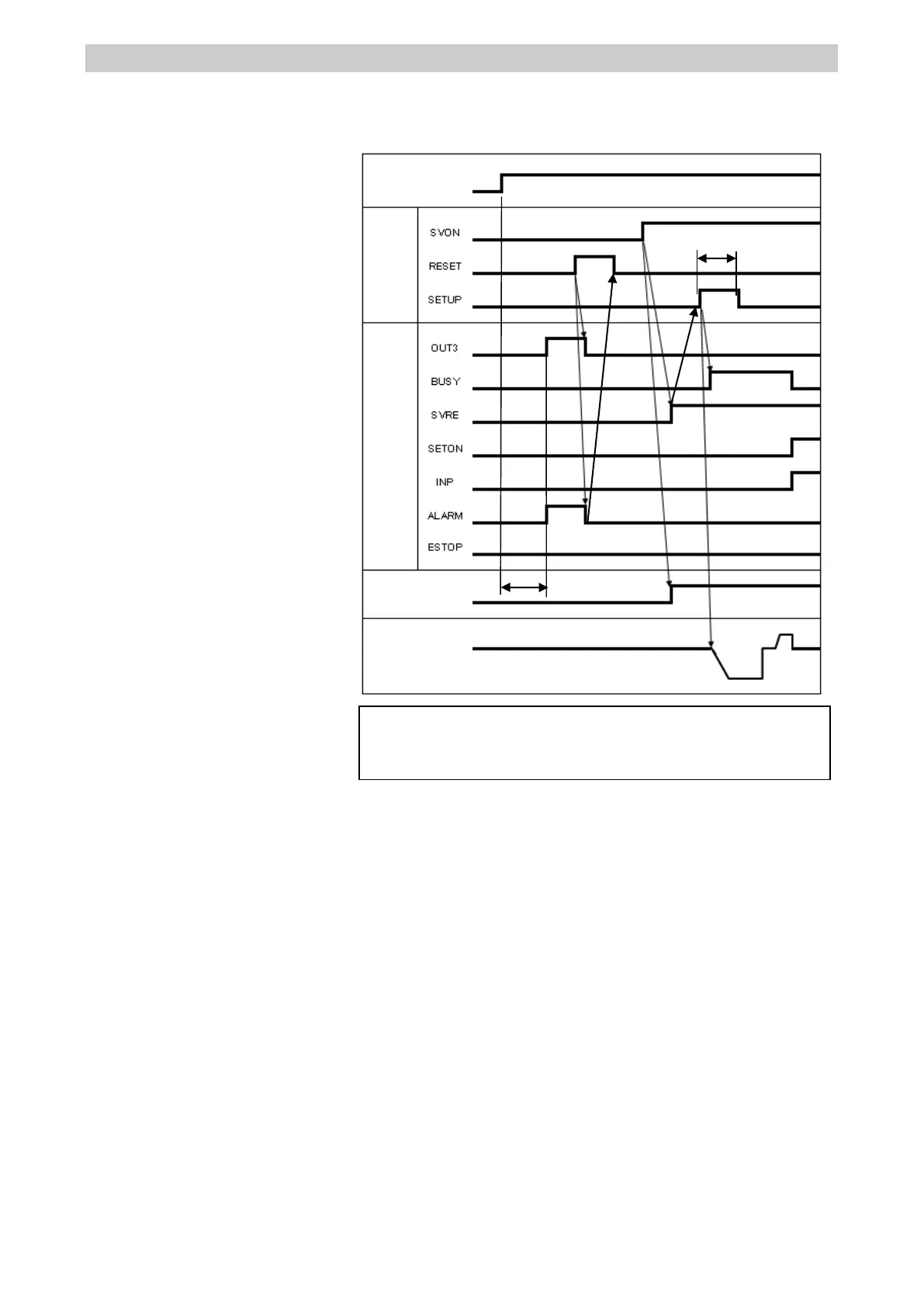
Please refer to the following [Procedures and Timing diagram] for each operation.
-Procedure- -Timing diagram-
1) Supply power
↓
2) ESTOP output is turned OFF
ALARM output is turned ON
OUT3 output is turned ON
([1-153: Absolute encoder ID does
not match controller data] alarm is
generated)
↓
3) RESET is turned ON.
↓
4) ALARM output is turned OFF.
↓
5) SVON input is turned ON
↓
6) SVRE output is turned ON.
* The actuator with lock is unlocked.
↓
7) SETUP input is turned ON.
↓
8) BUSY output is turned ON.
(Starts the operation.)
↓
9) SETON, INP output turns ON.
Return to origin is completed when
BUSY output is turned OFF.
When return to origin operation is
completed, DRIVE is available.

 Loading...


