EasyManuals Logo
Home>SMC Networks>Controller>JXC61

SMC Networks JXC61 User Manual

SMC Networks JXC61
167 pages
To Next Page IconTo Next Page
To Previous Page IconTo Previous Page
Page #144 background imageLoading...
Page #144 background image
- 59 -
12. Alarm Detection
The details of the alarm can be checked using the controller setting software or the teaching box.
Please refer to the manuals of the controller setting software or the teaching box for details of the alarms.
Please refer to section "12.2 Alarm details" of this manual on how to, deactivate the alarm.
12.1 Parallel output for the alarm group
In case of an alarm, this controller outputs a signal that informs the type of alarm.
Alarms are classified into 4 groups. When an alarm is generated, it is output in OUT0 to 3. OUT4 and
OUT5 are OFF.
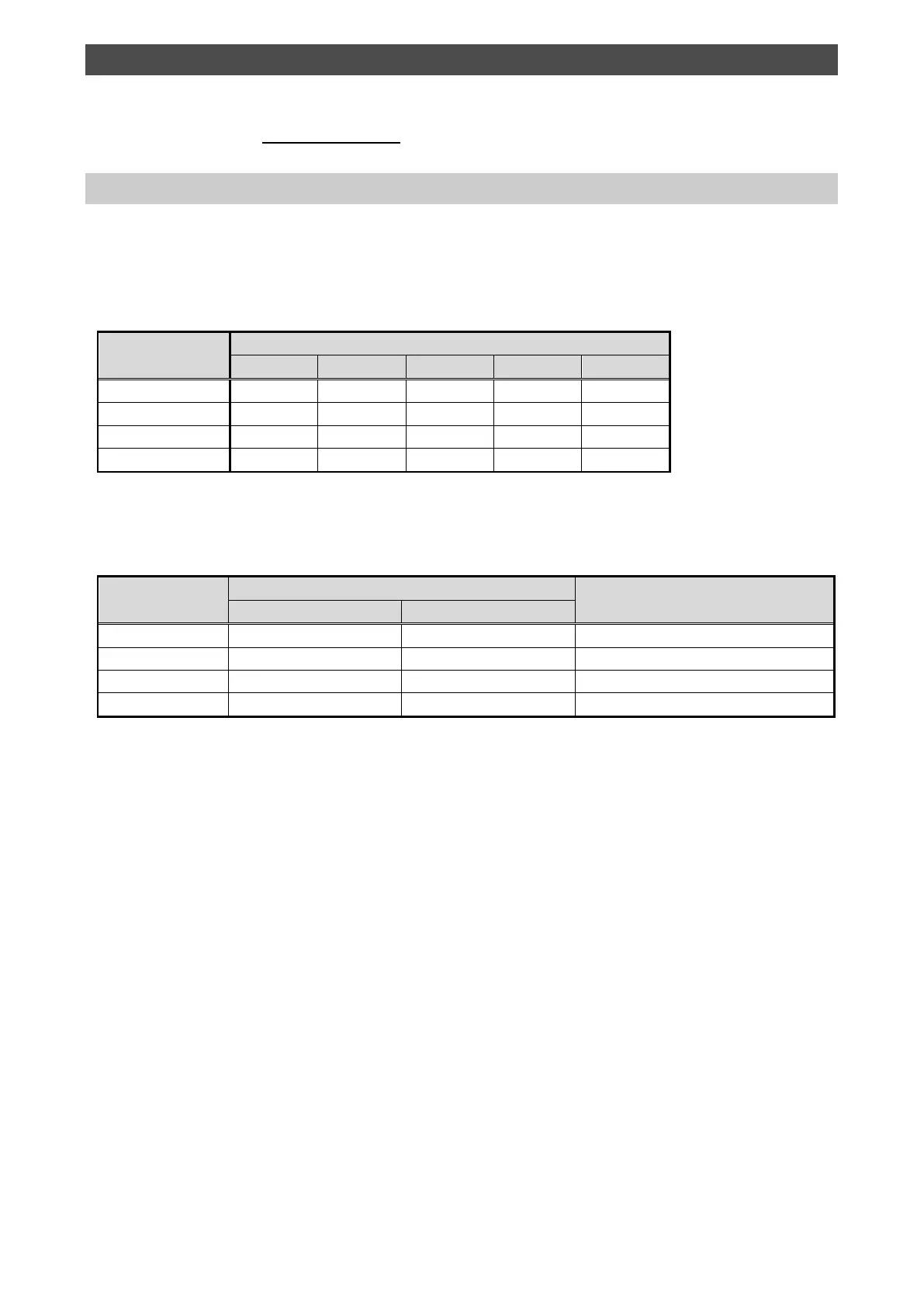
The status of output terminal for each alarm group is as follows:
Alarm group
Parallel output
*ALARM
OUT0
OUT1
OUT2
OUT3
Alarm group B
OFF
OFF
ON
OFF
OFF
Alarm group C
OFF
OFF
OFF
ON
OFF
Alarm group D
OFF
OFF
OFF
OFF
ON
Alarm group E
OFF
OFF
OFF
OFF
OFF
The "*ALARM" is expressed as negative-logic circuit.
When multiple alarms go off and there are different alarm groups, multiple OUT signals will turn on.
When the alarm has activated, the status of output terminal will be as follows:
Alarm group
Parallel output
Procedure of restart
SVRE
SETON
Alarm group B
There is no change.
There is no change.
RESET input
Alarm group C
There is no change.
There is no change.
RESET input
Alarm group D
OFF
There is no change
RESET input
Alarm group E
OFF
OFF
Power off Turn on the power again

Table of Contents

Questions and Answers:

Question and Answer IconNeed help?

Do you have a question about the SMC Networks JXC61 and is the answer not in the manual?

SMC Networks JXC61 Specifications

General IconGeneral
BrandSMC Networks
ModelJXC61
CategoryController
LanguageEnglish

Related product manuals