MENTOR 12 USER’S MANUAL SECTION 2: BASIC CONTROL – Page 36
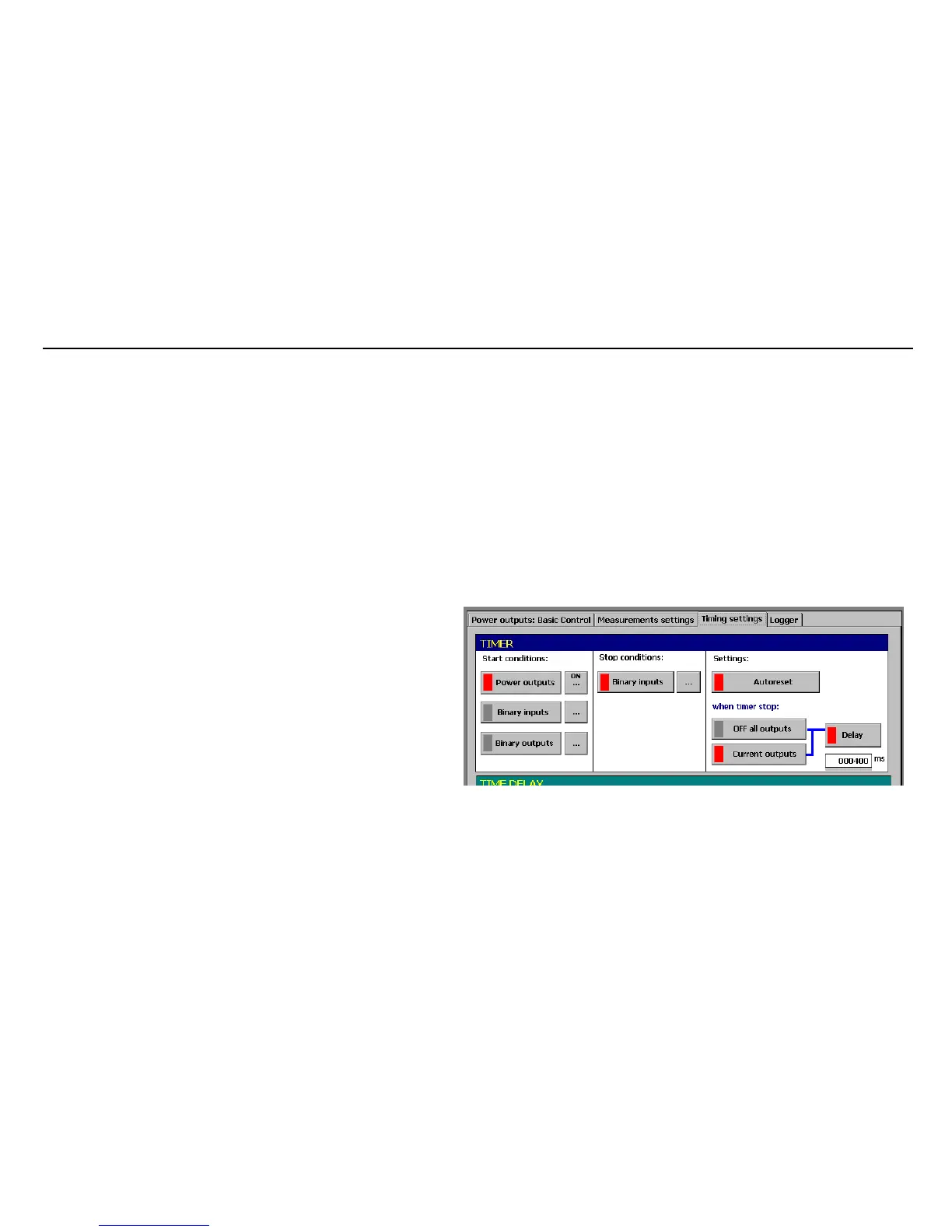
TIMER STOP conditions
The timer can only be stopped by the action of the Binary Inputs. If you press the
relative button it will be activated and the indicator will light up in red. With the button
situated on the right you will access a menu which permits selecting these inputs,
simply by pressing the terminals of the input you wish to use. Each one of the inputs
has a cyclic operation button associated with it, which selects its active mode between
UP (input activation) DOWN (input deactivation) or CHG (Change in input status). It can
also be selected if the action logic between the inputs is OR (the timer stop will be
activated when ANY of the inputs selected changes to the logic status selected) or AND
(the timer stop will be activated when ALL the inputs selected change to the logic status
selected)
TIMER Activation
• If you wish the timer to RESET and to start automatically
each time the start conditions selected occur, use the button
marked “Autoreset”. If you press the relative button it will be
activated and its indicator will light up in red. If you press it
again, it will be deactivated, and its indicator will change to
grey. If the “Autoreset” is deactivated the timer will start and
stop in agreement with the selected conditions and the time
unit will remain until the “Reset” button is pressed. If “Reset”
is not pressed and a new operation is carried out, the timer
will not start.
• Below the previous button there is a section called “when the
timer stops…” which permits selecting the desired action on
the outputs when the timer stops. “All outputs OFF” can be selected which
changes all the selected outputs, be they Voltage or Current, to OFF status,
or “Current outputs” which only changes the current outputs selected to OFF
status, leaving the voltage outputs active.
• The “Delay” button is on the right of these buttons. It is activated and
deactivated in cycles. When activated, a window is displayed to enter data
using the rotary knob, in this case in milliseconds, which defines the time that
 Loading...

