MENTOR 12 USER’S MANUAL SECTION 4 CONFIGURATION – Page 92
The Low Level Output buttons / indicators are located on the bottom of this window.
They work in the same way as the power outputs do.
If you want to make changes to the current configuration, use one of the appropriate
“CHANGE” buttons, which gives access to the controls that enable you to make these
changes, as described below.
When you press the “CHANGE” button corresponding to Current type outputs a similar
screen to the one below appears (depending on the number of channels installed):
Power Output Configuration
• Press on the button that indicates the number of sources you want to use.
• The different possible configurations appear on the right with the available
channels. Press on the one you wish to use.
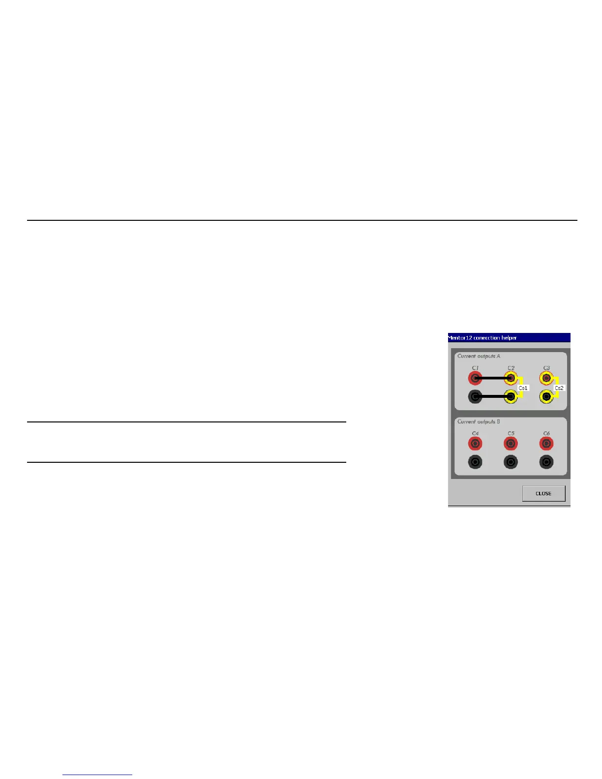
• Press the button marked “connection schematic”. A window appears
indicating the connections both to the charge and between the different
equipment outputs, if applicable.
WARNING: Strictly follow the connection instructions. The terminals that appear
without connections on the diagram must be left free. The terminals
that appear connected to others must be connected as indicated. If
you do not do it like this, you will not obtain the correct results.
Configuration of the Low Level Outputs
If you wish to use the Low Level Outputs, you must select the ones you wish to use and
configure them in turn.
Bear in mind that the number of Low Level Outputs available depends on the
configuration of the Power Outputs.
In each case, the program will only show you the Low Level Outputs available. If you
wish to use more than the ones that appear (maximum 3), you must modify the power
output configuration so less Sources are used.
 Loading...

