MENTOR 12 US SECTION 3: ADVANCED CONTROL – Page 54 ER’S MANUAL
• Blue window on the post-fault area of the graphic: you must enter the duration
of the post-fault in milliseconds, clicking on this and using the digit adjustment
selection arrows and the rotary knob.
• Blue window in the area of the graphic marked
Trip: you must enter the switch time to be
simulated in milliseconds. That is, it defines the
time lag between the trip signal of the relay
tested and the effective disappearance of the
voltages and/or currents in the output (Switch
opening).
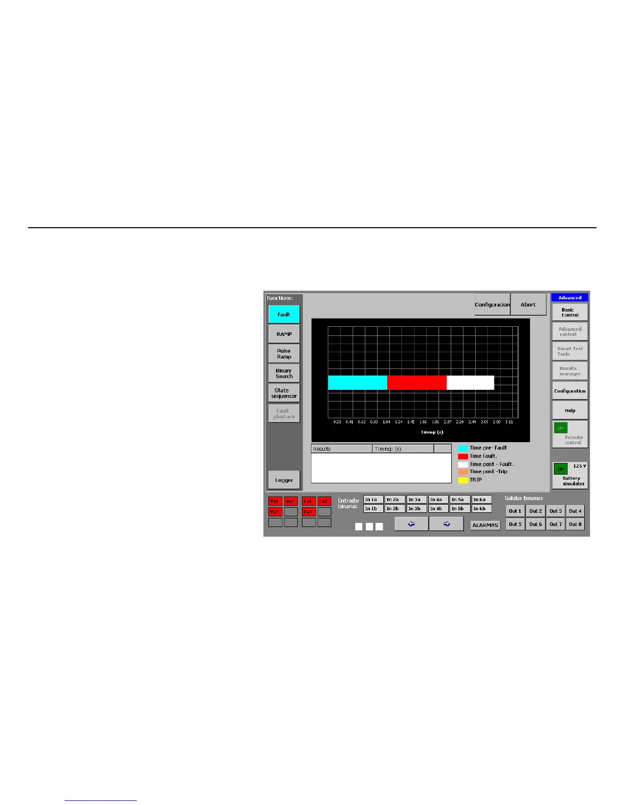
Fault Execution: there have been no trips
Execution
After correctly configuring the fault as described above,
the system is ready to execute it. Proceed as follows:
• Press the key marked “Execute” on the upper
right-hand corner of the configuration screen.
The window will change to the execution screen and the
test will be carried out. It may take a few seconds for the
test to start, due to the process time.
 Loading...

