Raptor
36
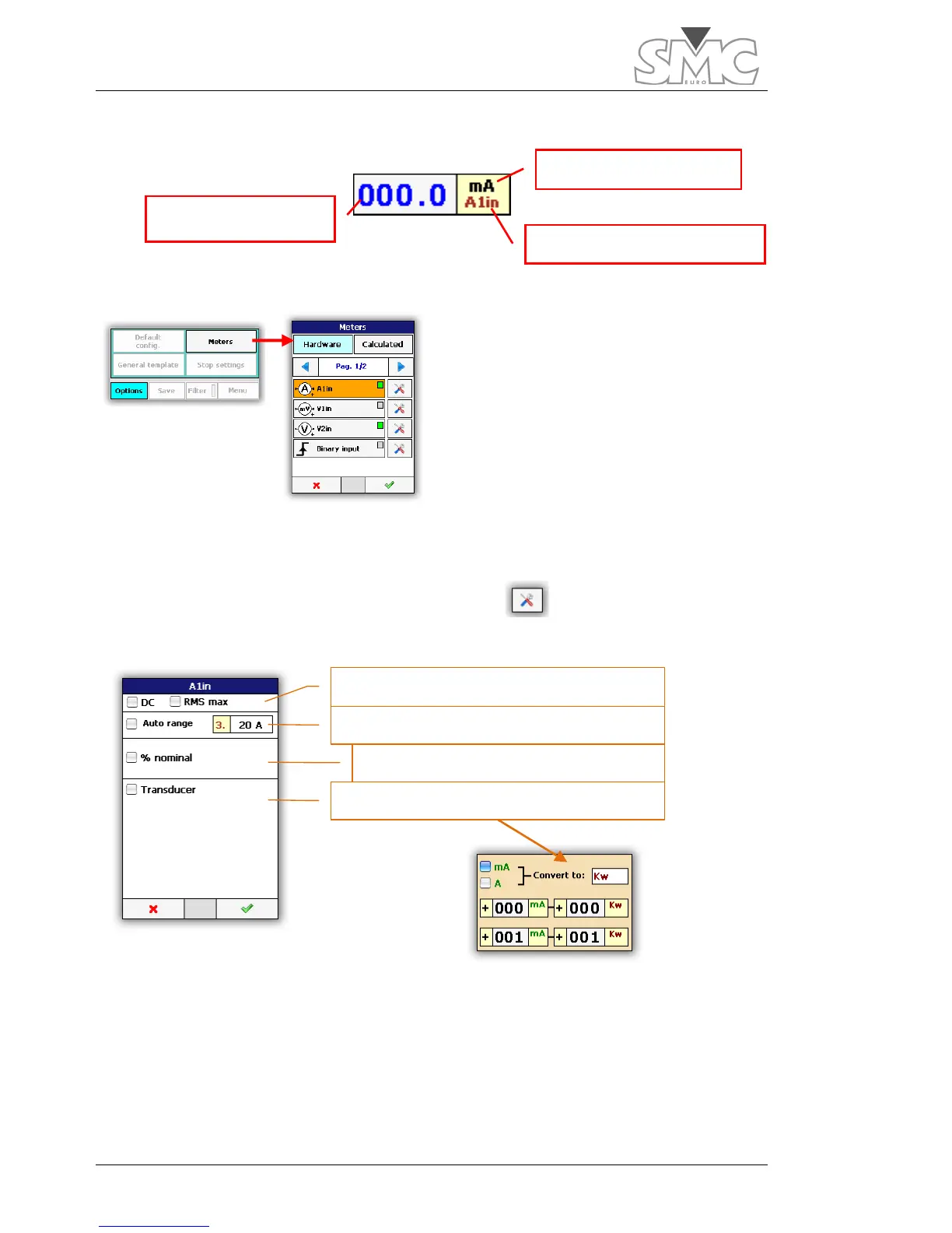
If the value of the measurement is in blue, it indicates the automatic range setting.
To select the ‘Hardware’ measurements,
proceed as indicated in the figure.
It can be seen in the image, that the
‘Hardware’ measurements are selected.
The ‘Calculated’ measurements are
described in the next section. There are two
selection pages.
The green/grey LED of each meter indicates if the measurement is selected for display.
To access the measurement setting, tap on
The A1in, V1in and V2in measurements are configured as follows:
The transducer mode allows you to adjust the magnitude shown on screen to the
transducer’s conversion characteristics, thereby allowing the units, scale and offset to be
changed.
Phase measurements have no configuration.

 Loading...
