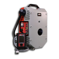
Raptor
84
If you are not sure about the possible reaction of the generator regulation on removing
burden, do not follow this recommendation.
Number of turns.
In traditional primary injection equipment, you must adapt to the different output ranges.
If you choose one with greater voltage, you will have less current or vice-versa. The same
occurs in the Raptor system, but with the number of turns. If you wind 2 turns you will
have double the voltage and half the current; if you wind 3, you will have triple the
voltage and a third of the current. The difference is that in the Raptor system, the number
of output ranges is much greater, enabling you to adapt more to the voltage/current
need.
Thus, the best adaptation will always be achieved when you can wind the maximum
number of turns, for the required current and time.
Number of Raptor-SL units
The Raptor-SL slave units do not determine the maximum current that the system can
handle, but they do provide voltage for the pass-through winding. Each unit will increase
the available power by 5KVA in permanent regime, which is the equivalent to
approximately between 0.6 and 1.3V per turn (depending on the regime). When you
wish to work with high currents/power, the best solution is to add these units to the
system.
Minimum load impedance
This is the other factor that attention must be paid to when maximising the available
power/current. Normally, in tests with high currents, the limitation is determined by the
connections used to join the injection system to the burden to be tested, as the latter,
apart from being fixed, is negligible.
Distance to burden.
The circuit impedance (both the resistive part and the inductive part) is directly
proportional to the distance that exists between the burden and the injection system. Try
to shorten this distance as much as possible. Sometimes it is more advisable to have
several shorter cables than one long one. In this way you will not be forced to user longer
ones than necessary. You can always place them in series for greater distances or place
them in parallel to increase the cross-section.
Due to the modular construction of the Raptor system and to the reduced weight of each
unit, sometimes it is more practical to raise the units close to the burden, for example, on
a forklift truck, than coping with the weight and cross-section of the cables.
The cross-section of the secondary conductor.
In order to minimise the resistance of the injection circuit, it is recommended to use the
largest secondary cross-section possible, when you are optimising the power / current.
The hole diameter for the pass-through winding of the Raptor system is optimised for the
current density to be low.

 Loading...