Users Guide
25
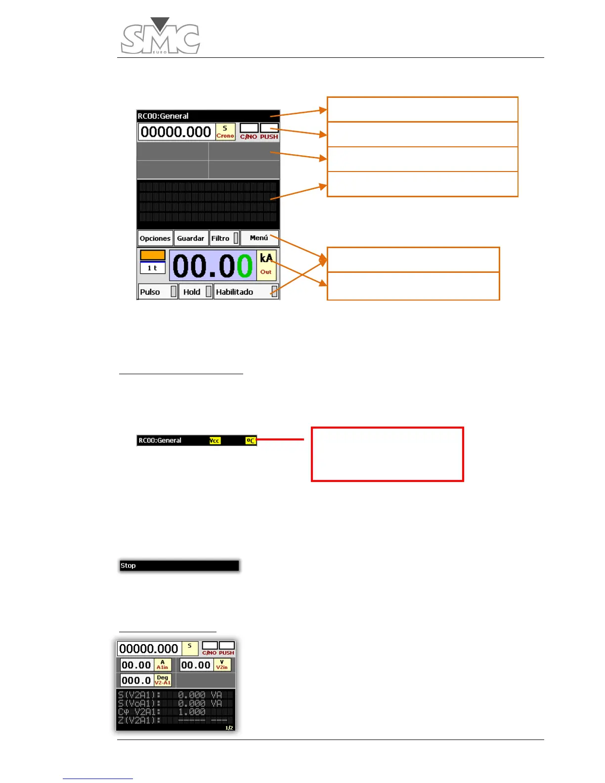
Main touch screen
The main screen is divided into three main zones according to their functionality: Help
and alarms scroll bar, measurements and injection.
Help and alarms scroll bar
This zone has a dual functionality: showing a help text for some parts of the screen and
showing the alarm indicators.
Alarms. The alarm indicators are displayed in this zone. There is an indicator for power
supply failure (
VDC), Temperature (º C), line voltage (Vln) and overload (Ovl). The
indicators are highlighted with a yellow background. The preceding image shows some
indicators.
Help texts. When tapping on certain controls of the screen,
an indicative text of their function is shown for a few
seconds, thereby replacing the name of the system. The image shows the text after
tapping on the Stop indicator.
Measurements zone.
The controls that show the measurements taken by the
equipment are located here. They can be
hardware
measurements (direct readings made by the Raptor-MS) or
calculated
measurements (processed based on
hardware
meters). You can modify the meters you want to be displayed
Indicator with temperature
alarm

 Loading...
