Raptor
26
at any time, although two of them (the time meter and the stop condition) are always
visible.
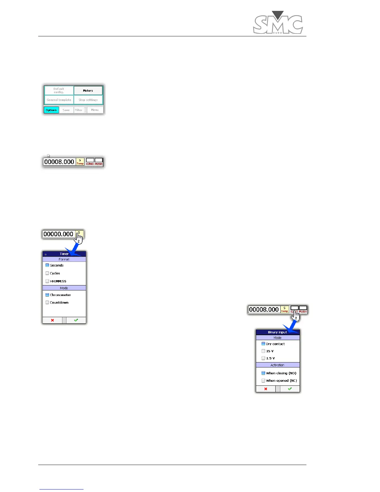
Meter selection.
To add or remove meters, tap on the
options
button and then
meters
.
A screen will be displayed where you can select the
hardware and calculated meters. Many of the meters also have
a button on their right-hand side to access the meter’s settings. A
maximum of four
hardware
meters can be displayed. There is no limit to the number of
visible calculated meters.
Time meter.
It shows the time elapsed as from the moment when power
generation starts until it turns off or until the configured stop
condition is reached. This meter is always visible.
It can be displayed in seconds, in cycles or in the HH:MM:SS format, and it can work as
a chronometer or a timer. When working as a timer, generation is shut down when zero
is reached.
To configure the time meter, tap twice on the time control, and you
will access the options window.
Binary input indicator
It shows the status of the binary input. The indicator lights up red
when it is active.
And it is white when inactive.
To configure the binary input indicator, tap twice on the control.
In Mode section you can select between dry contact or voltage input. In voltage mode
can choose between two detection thresholds. These levels do not indicate the maximum
voltage level applied to the input, which is 250V.

 Loading...
