Users Guide
75
The Vccr value obtained must be lower than the available in the equipment , 230 V. If it
is higher, replace Ired of the formula with a lower value until the Vccr value is less than
230 V.
Once you know these values, connect the equipment output and gently adjust the output
voltage until you obtain the value READ on display V2, equal to Vccr. If the real short-
circuited impedance coincides with the theoretic impedance, you should be reading a
current value on display A1 that is very similar to Ired.
You will be able to read all the values indicated by the meters during the injection.
If the measurements are seen to be unstable, and their values are continuously changing,
use the FILTER option to see the most stable values.
To stop the injection and finish the test, simply click on the button of the dial.
Save the results with a comment, indicating that this is the measurement H1H2 and
repeat the process with the remaining phase loops.
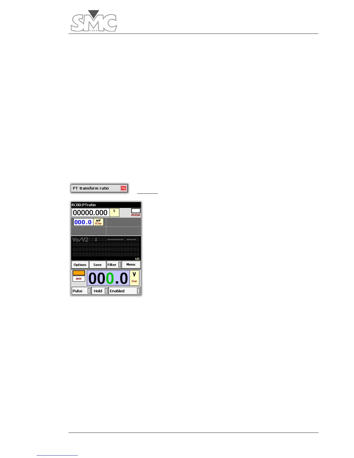
PT ratio
This template permits measuring the voltage ratio between
the primary or High winding and the relative secondary or
Low winding of a Power (PT) or Distribution Transformer.
However, unless the transformer is single-phase or three-
phase with connection group YNyn…, this voltage ratio will
not coincide with the transformation ratio that appears on
the characteristics plate of the PT.
To convert the voltage ratio measured at this transformation
ratio, several calculations are required, as well as the
execution of tests with different connections to the PT. These
calculations and connections depend on the PT group, and
as there are many different ones, they are not described in this Handbook, and are left to
the discretion of the equipment operator.
If this calculation method is required, please contact us and we will give it to you.
Template configuration:
The template is configured as follows:
• Generator: Auxiliary power output. Voltage Mode
• Time display: As chronometer in seconds. Stop mode: Push on dial
• V2in input voltage meter in Volts. Auto Mode (voltage measurement injected
into Low voltage winding).
• Voltage ratio meter Vo/V2

 Loading...
