For this test to offer you correct results, it
is important not to leave any burden not
measured, so you must proceed to lift
one of the CT secondary physical
connections from the bushing plate of
the actual transformer. Proceed with
caution when carrying out this operation,
making very sure that no primary current
passes through the CT. Although the test
does not require much time, it is very
advisable, after lifting both cables from
the CT bushing plate, to make a bridge
between these bushings with a cable so that, if for any reason the CT receives current in
its primary, its secondary is always short-circuited.
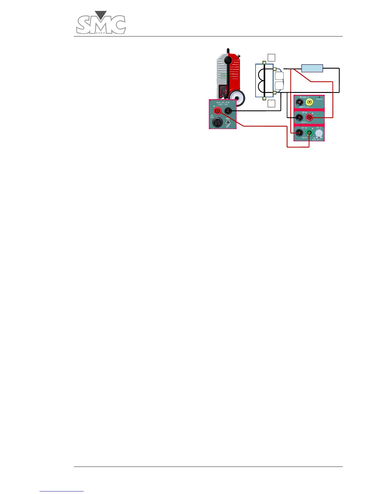
Once the secondary connection cables are available, connect as follows:
1. Connect the BLACK tap of the auxiliary output of the RAPTOR, using a test
cable, to the connection cable of the secondary corresponding to S2. Make
sure that they are firmly connected together.
2. Connect the RED tap of the auxiliary output of the RAPTOR , using a test
cable, directly to the GREEN tap of the current measurement input A1 of the
actual equipment.
3. Connect the BLACK tap of the current measurement input A1 of the
equipment, using a test cable, to the connection cable of the secondary
corresponding to S1. Make sure that they are firmly connected together.
4. Connect the RED tap of the voltage measurement input V2 of the equipment
to the connection cable of the secondary corresponding to S1, making sure
that it is connected downstream from the current injection connection*.
5. Connect the BLACK tap of the voltage measurement input V2 of the
equipment to the connection cable of the secondary corresponding to S2,
making sure that it is connected upstream from the current connection*.
* This is a 4-wire measurement. If you connect the voltage measurement cables
incorrectly, you may include in it the impedance measurement of the actual test
connection, which is not desirable.

 Loading...
