Template configuration:
The template is configured as follows:
• Generator: Auxiliary power output. Voltage Mode
• Time display: As chronometer in seconds. Stop mode: Push on dial
• V2in input voltage meter in Volts. Auto Mode (voltage measurement injected
into the burden).
• A1in input current meter in Amps. Auto Mode (Current measurement in
burden).
• Phase angle meter between current measured in A1in and the voltage
measured in V2in. (Burden phase angle and polarity in degrees)
• V2/V1 ratio meter which is shown as a result of the division between the two
voltages.
• Apparent power (S) meter in VA
• Power factor meter (cos phi) of the burden.
• Impedance (Z) meter of the burden in ohms.
Connections:
The Auxiliary Output Power
Generator is used in voltage
mode to carry out this test,
feeding the burden connected
to the secondary burden of the
VT and measuring the current it
consumes.
The connection cables must be
disconnected from the VT
secondary, taking the appropriate precautions, thus insulating this secondary. The
injection of the test voltage will be carried out on these cables.
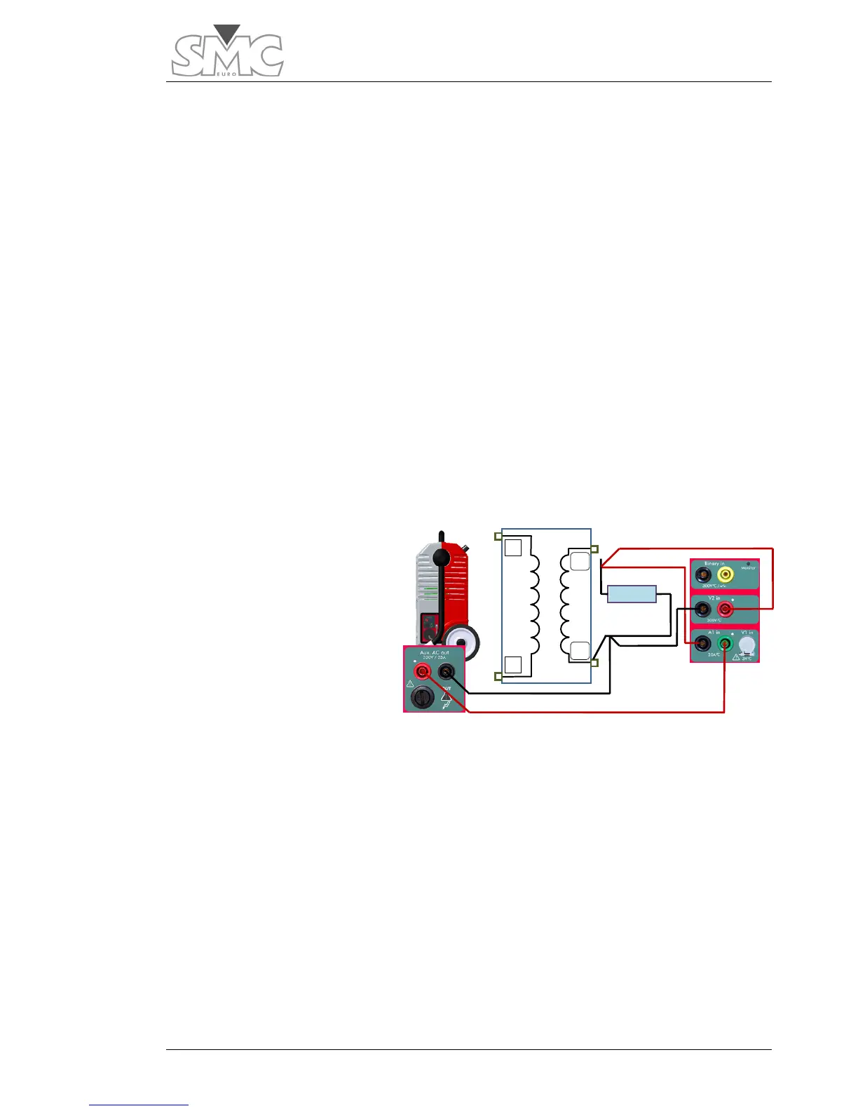
Connect as follows:
1. Remove connection from secondary X1
2. Connect the BLACK bushing of the Auxiliary Output to the cable that was
connected at point X2 of the VT.
3. Connect the RED bushing of the Auxiliary Output to the GREEN bushing of
the current measurement input A1.
4. Connect the BLACK bushing of the current measurement input A1 to the
cable that was connected at point X1 of the VT.
5. Connect the RED bushing of the voltage measurement input V2 to the cable
that was connected at point X1 of the VT.

 Loading...
