Users Guide
81
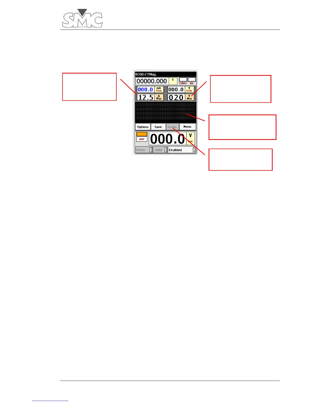
Function configuration
This is shown on the image below:
Connections
All the connection are made in the secondary winding (1 or 5 A) of the CT. The Primary
winding must be left OPEN.
Connect the BLACK bushing of the Auxiliary Generator of the equipment to the bushing
of the secondary of the CT, marked S1.
Connect the RED bushing of the Auxiliary Generator of the equipment to the GREEN
bushing of the current measurement input A1in.
Connect the BLACK bushing of the current measurement input A1in to the bushing of the
secondary of the CT marked S2.
Connect bushing S1 of the CT to the BLACK bushing of the voltage measurement input
V2in.
Connect bushing S2 of the CT to the RED bushing of the voltage measurement input
V2in.
Test
The function is automatic, so the operator only has to enter the maximum I and
maximum V values into the relative controls, and simply click on the dial to start the test.
If the knee point is found, this will be displayed on the screen. Do not interrupt the test as
it has not finished. Always let the demagnetisation process end.
The maximum voltage value entered is especially important. If you enter a very high value
with respect to the value that would really correspond to the CT tested, the knee point will
Maximum current
permitted to

 Loading...
