EasyManuals Logo
Home>Sony>Stereo System>MHC-V11

Sony MHC-V11 Service Manual

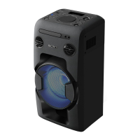
Sony MHC-V11
54 pages
To Next Page IconTo Next Page
To Previous Page IconTo Previous Page
Page #5 background imageLoading...
Page #5 background image
MHC-V11
5
SECTION 2
DISASSEMBLY
This set can be disassembled in the order shown below.
2-1. DISASSEMBLY FLOW
SET
2-2. LEFT SIDE COVER,
RIGHT SIDE COVER
(Page 6)
2-3. TOP COVER BLOCK
(Page 7)
2-4. MAIN VOLUME KNOB,
MIC VOLUME KNOB
(Page 8)
2-5. CONTROL BOARD
(Page 9)
2-7. LOADER (CDM1)
(Page 10)
2-17. PSU BOARD
(Page 19)
2-8. BT BOARD
(Page 11)
2-9. CHASSIS BLOCK
(Page 12)
2-15. LOADER BLOCK
(Page 18)
2-16. MAIN BOARD
(Page 19)
2-10. FRONT PANEL BLOCK
(Page 13)
2-14. WOOFER UNIT (SP1)
(Page 17)
2-13. LED A BOARD,
LED B BOARD
(Page 16)
2-12. TWEETER UNIT (SP2, SP3)
(Page 15)
2-11. TWEETER UNIT WIRE
(Page 14)
2-6. TOP COVER ASSY,
NFC BOARD
(Page 9)
JIG
When disassembling the unit, use the following
jig for speaker removal.
Part No. Description
J-2501-238-A JIG FOR SPEAKER REMOVAL

Table of Contents

Other manuals for Sony MHC-V11

Questions and Answers:

Question and Answer IconNeed help?

Do you have a question about the Sony MHC-V11 and is the answer not in the manual?

Sony MHC-V11 Specifications

General IconGeneral
BrandSony
ModelMHC-V11
CategoryStereo System
LanguageEnglish

Related product manuals