MHC-V11
9
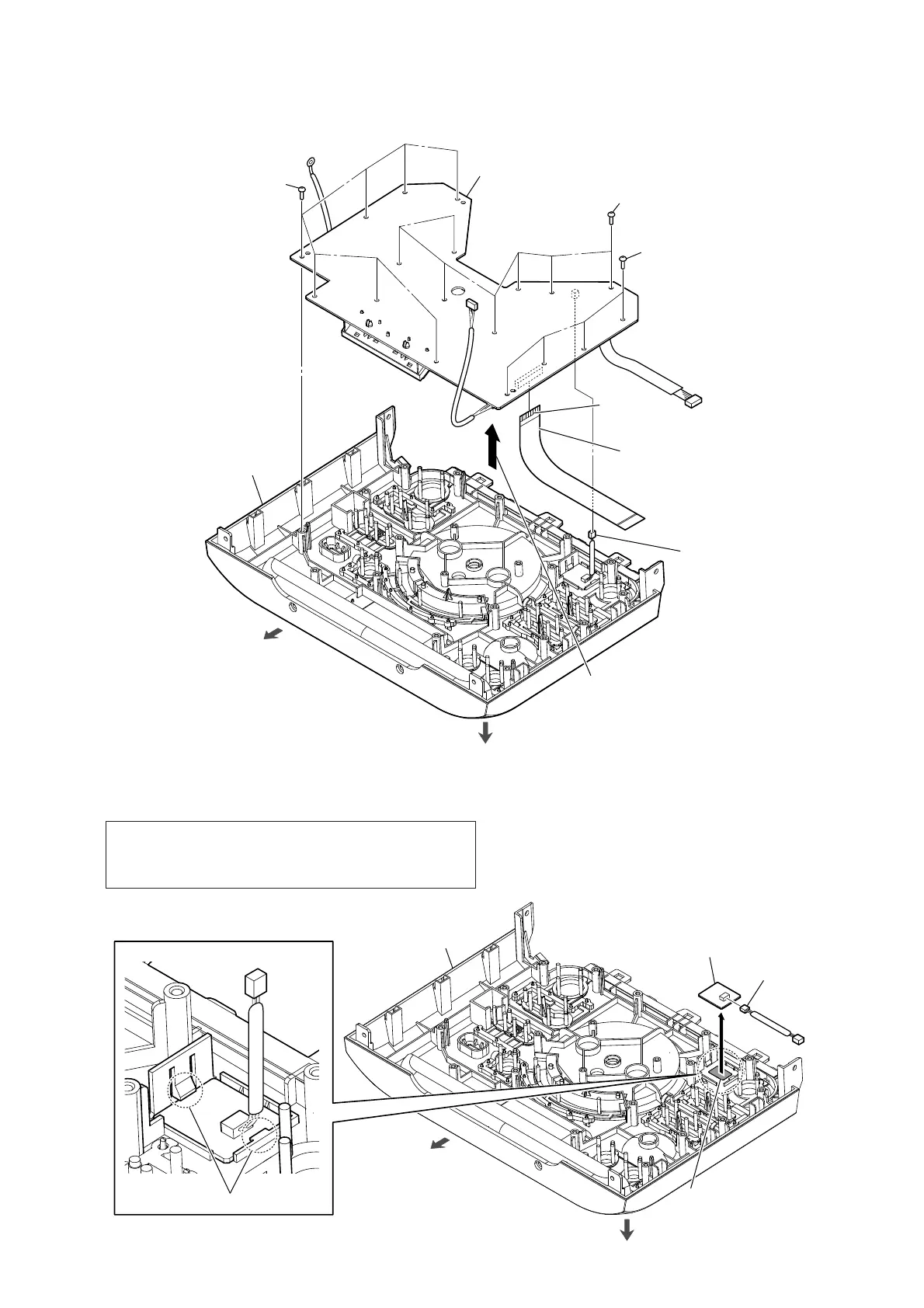
2-5. CONTROL BOARD
2-6. TOP COVER ASSY, NFC BOARD
1 seven screws
top cover block
1 seven screws
1 four screws
rear side
2
Lift up the CONTROL board block
in the direction of the arrow.
3 connector (2P)
(XP2)
4 FFC (20P)
(XP1)
5 CONTROL board
top side
This side is
the terminal side.
rear side
5 NFC board
3
top cover assy
1 two claws
2 Peel the NFC board block
off of the adhesive sheet.
4 connector (2P)
(XP15)
top side
Note: When replacing the NFC board, be sure to replace the BT board
and the NFC board simultaneously. The NFC board cannot re-
place with single. Among the repair parts, the BT board and the
NFC board is supplied as one unit.

 Loading...