MHC-V3/V4D
10
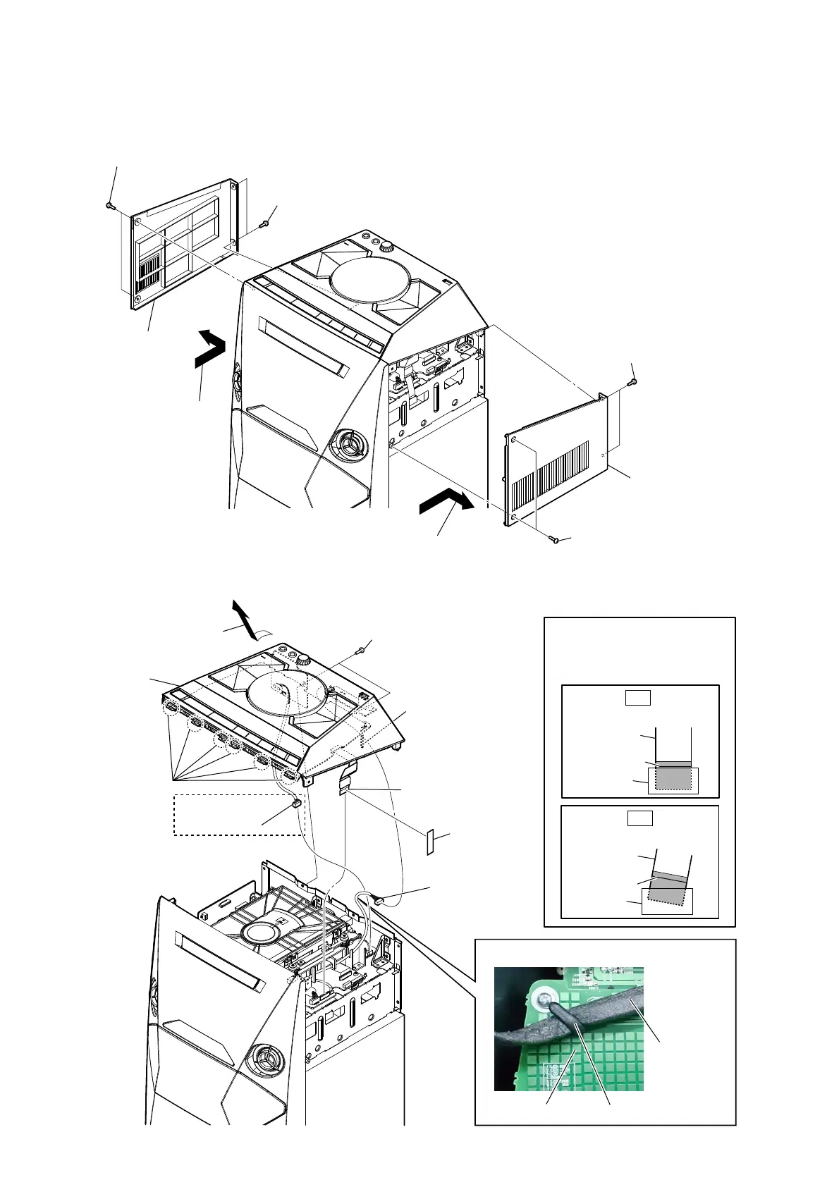
Note: Follow the disassembly procedure in the numerical order given.
2-2. SIDE L, R PANEL
2-3. TOP PANEL BLOCK
1 two screws
(+BVTP 3 u 10)
1 two screws
(+BVTP 3 u 10)
2 two screws
(+BVTP 3 u 10)
2 two screws
(+BVTP 3 u 10)
3 Remove the panel, side L
in the direction of the arrow.
4 panel, side L
3 Remove the panel, side R
in the direction of the arrow.
4 panel, side R
Ver. 1.3
1 two screws
(+BVTP 3 u 10)
9 panel, top block
3 six claws
2 filament tape
4 Remove the panel, top block
in the direction of the arrow.
5 wire (flat type) (13 core)
(CN114)
6 Remove the USB wire
from the clamp (L35)
7 CN6001 (5P)
8 CN3003 (4P)
Note:
When installing the wire
(flat type), ensure that the
colored line is not slanted
after insertion.
colored line
Insert is straight to the interior.
wire (flat type)
connector
OK
colored line
Insert is incline
wire (flat type)
connector
NG
(V4D)
USB Wire
(CN6001) (5P)
:LUHVHWWLQJ
PANEL board clamp (L35)

 Loading...