MHC-V3/V4D
23
Under the guide
Under the guide
(Fold area)
,QVWDOODWLRQRIZLUHIODWW\SHFRUHDQGZLUHIODWW\SHFRUH
Note:
This illustration sees the loading assy (T) from bottom side.
1 wire (flat type) (24 core)
2 Through the hole
3 Through the hole
4
terminal face
loading assy (T)
7 wire (flat type)
(24 core)
6 holder, FFC
5 three claws
5 two claws
9 wire (flat type)
(5 core)
0 tape
8 tape
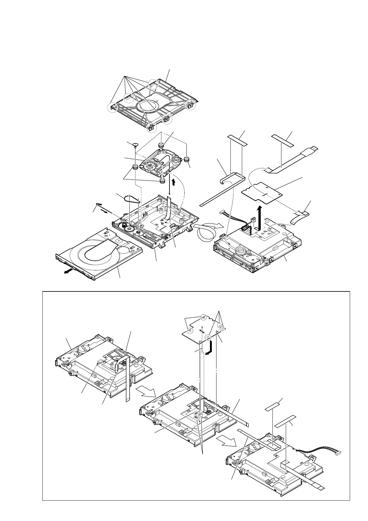
2-16. SERVICE, OPTICAL DEVICE(7G), WIRE (FLAT TYPE)
Note : Before disconnecting the wire (fl at type) (24 core) of optical pick-up block, solder the short-land.
8 four insulator screws
7 connector
qa insulator
6 belt
3 Insert the thin
wire (clip etc.).
5 tray
qs service,
optical device(7G)
qa insulator
qa insulator
qh
ql wire (flat type)
(24 core)
qk tape
qf tape
1 six claws
4
9
0
2 chuck holder assy (T)
qg wire (flat type)
(5 core)
– Bottom view –
loading assy (T)
qd base, lo assy
qj holder, FFC
Ver. 1.1

 Loading...