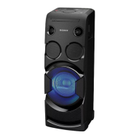
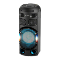
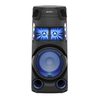
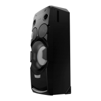
MHC-V3/V4D
4
SECTION 1
SERVICING NOTES
Notes on chip component replacement
• Never reuse a disconnected chip component.
• Notice that the minus side of a tantalum capacitor may be
damaged by heat.
Flexible Circuit Board Repairing
• Keep the temperature of the soldering iron around 270 °C
during repairing.
• Do not touch the soldering iron on the same conductor of the
circuit board (within 3 times).
• Be careful not to apply force on the conductor when soldering
or unsoldering.
UNLEADED SOLDER
Boards requiring use of unleaded solder are printed with the
leadfree mark (LF) indicating the solder contains no lead.
(Caution: Some printed circuit boards may not come printed with
the lead free mark due to their particular size)
: LEAD FREE MARK
Unleaded solder has the following characteristics.
• Unleaded solder melts at a temperature about 40 °C higher
than ordinary solder.
Ordinary soldering irons can be used but the iron tip has to be
applied to the solder joint for a slightly longer time.
Soldering irons using a temperature regulator should be set to
about 350 °C.
Caution: The printed pattern (copper foil) may peel away if
the heated tip is applied for too long, so be careful!
• Strong viscosity
Unleaded solder is more viscous (sticky, less prone to fl ow)
than ordinary solder so use caution not to let solder bridges
occur such as on IC pins, etc.
• Usable with ordinary solder
It is best to use only unleaded solder but unleaded solder may
also be added to ordinary solder.
CAUTION
Use of controls or adjustments or performance of procedures
other than those specifi ed herein may result in hazardous radiation
exposure.
NOTES ON HANDLING THE OPTICAL PICK-UP BLOCK
OR BASE UNIT
The laser diode in the optical pick-up block may suffer electrostatic
break-down because of the potential difference generated by the
charged electrostatic load, etc. on clothing and the human body.
During repair, pay attention to electrostatic break-down and also
use the procedure in the printed matter which is included in the
repair parts.
The fl exible board is easily damaged and should be handled with
care.
NOTES ON LASER DIODE EMISSION CHECK
The laser beam on this model is concentrated so as to be focused
on the disc refl ective surface by the objective lens in the optical
pickup block. Therefore, when checking the laser diode emission,
observe from more than 30 cm away from the objective lens.
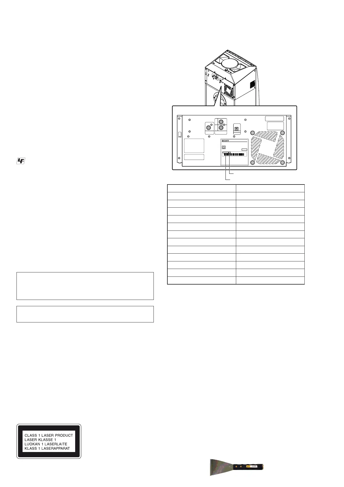
MODEL IDENTIFICATION
This appliance is classifi ed as a
CLASS 1 LASER product by
IEC60825-1:2007. This marking
is located on the rear exterior.
Model Part No.
V3: E2
4-536-755-0[]
V3: AUS
4-536-756-0[]
V3: E51
4-536-759-0[]
V4D: E2
4-539-781-0[]
V4D: TH
4-539-782-0[]
V4D: E4
4-539-783-0[]
V4D: EA
4-539-784-0[]
V4D: SAF
4-544-279-0[]
V4D: MY
4-544-280-0[]
V4D: E51
4-566-622-0[]
V4D: AR
4-566-623-0[]
V4D: MX
4-566-624-0[]
• Abbreviation
AR : Argentina model
AUS : Australian model
E2 : 120 V AC area in E model
E4 : African model
E51 : Chilean and Peruvian models
EA : Saudi Arabia model
MX : Mexican model
MY : Malaysia model
SAF : South African model
TH : Thai model
PLAYABLE DISCS
• AUDIO CD
• CD-R/CD-RW/DVD-R/DVD-RW
– audio data
– MP3 fi les that conforms to ISO9660 Level 1/Level 2, or
Joliet (expansion format).
Notes
• MP3 (MPEG 1 Audio Layer-3) is a standard format defi ned
by ISO (International Organization for Standardization) which
compresses audio data. MP3 fi les must be in MPEG 1 Audio
Layer-3 format.
• The system can only play back MP3 fi les that have a fi le
extension of “.mp3”.
• JIG
When disassembling the set, use the following jig (for front
panel removal).
Part No.: J-2501-238-A JIG FOR SPEAKER REMOVAL
– Back Panel –
PART No.
Destination code
SISTEMA DE AUDIO PARA EL HOGAR
AC 220-240V ~ 50Hz 120W
N
O
SERIE 00000634-536-759-01 E51
HECHO EN MALASIA
CERTIFICADO N
O
X-XXX-XX-XXXX
R
03/2014
MODELO MHC-V3
Ver. 1.5

 Loading...