MHC-V50/V50D
25
SECTION 4
ELECTRICAL CHECK
Procedure:
1. Turn the power on.
2. Input the following signal from Signal Generator to FM
antenna input directly.
Carrier frequency : A = 87.5 MHz, B = 98 MHz, C = 108 MHz
Deviation : 75 kHz
Modulation : 1 kHz
ANT input : 35 dBu (EMF)
Note: Please use 75 ohm “coaxial cable” to connect SG and the
set. You cannot use video cable for checking.
Please use SG whose output impedance is 75 ohm.
3. Set to FM tuner function and scan the input FM signal with
automatic scanning.
4. Confi rm that input Frequency of A, B and C detected and
automatic scanning stops.
The stop of automatic scanning means “The station signal is
received in good condition”.
CD/DVD SECTION
Note:
1. CD/DVD block is basically constructed to operate without ad-
justment.
2. Use YEDS-18 disc (Part No. 3-702-101-01) unless otherwise
indicated.
3. Use an oscilloscope with more than 10 MΩ impedance.
4. Clean the object lens by an applicator with neutral detergent
when the signal level is low than specifi ed value with the fol-
lowing check.
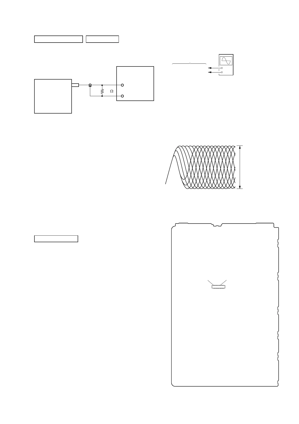
FM AUTO STOP CHECK
signal
generator
set
+
–
75
TUNER SECTION
0 dB = 1 ȝV
FOCUS BIAS CHECK
+
–
MOTHERBOARD board
oscilloscope
(DC range)
CN302 pin 17 (RF)
CN302 pin 1 (GND)
Procedure:
1. Connect the oscilloscope to CN302 pin 17 (RF) and CN302
pin 1 (GND) on the MOTHERBOARD board.
2. Press the [
1
] button to turn the power on, and touch the
[FUNCTION] touch key to select CD/DVD function.
3. Set the test disc (CD: YEDS-18) on the tray and touch [B]
touch key to playback.
4. Confi rm that oscilloscope waveform is as shown in the fi gure
below (eye pattern).
A good eye pattern means that the diamond shape () in the
center of the waveform can be clearly distinguished.
VOLT/DIV: 200 mV
TIME/DIV: 500 ns
level:
1.1 ± 0.25 Vp-p (DVDSL)
1.0 ± 0.25 Vp-p (CD)
Checking Location:
CN302
pin 17 (RF)pin 1 (GND)
– MOTHERBOARD Board (Component Side) –
 Loading...