MHC-V50/V50D
26
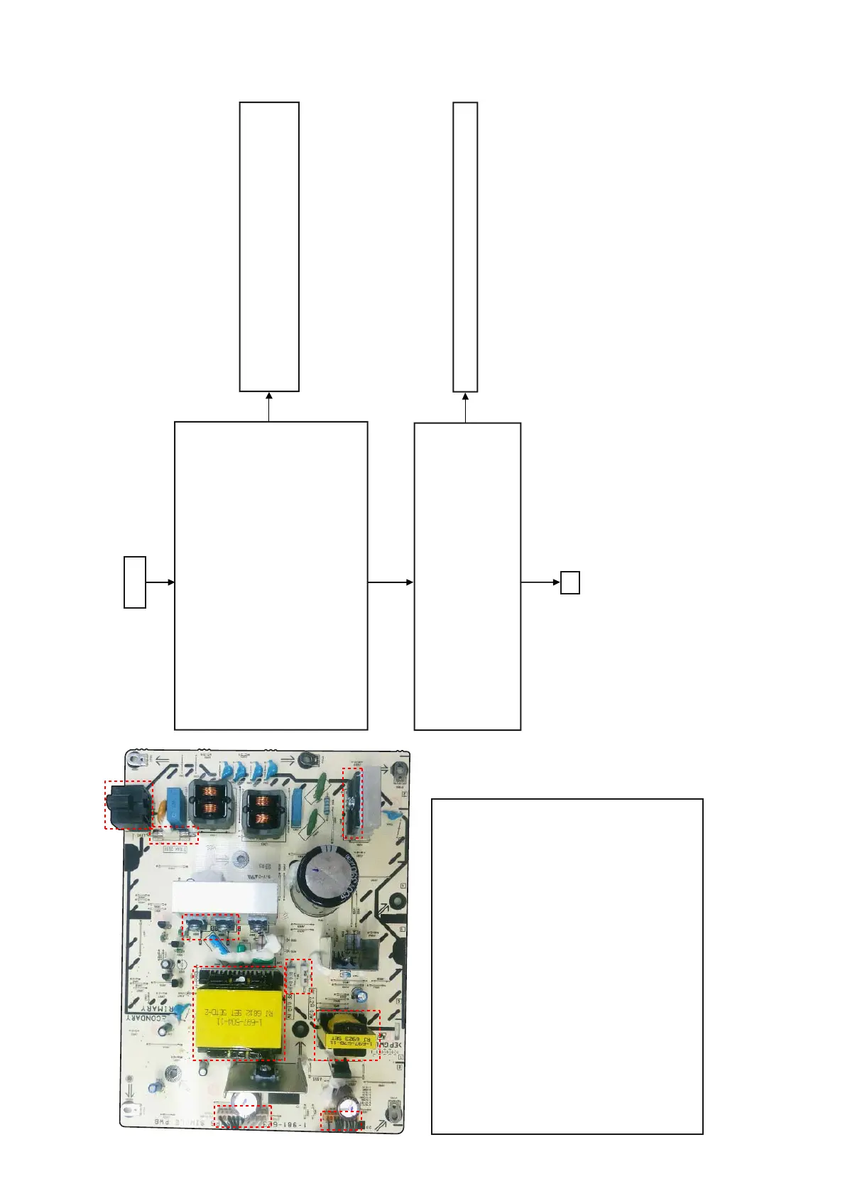
SMPS Board Diagnosis Flow (1/2)
SECTION 5
TROUBLESHOOTING
(4)
(6)
(3)
(7)
(9)
(5)
(8)
(2)
(1)
The output from SMPS board check as below.
AC IN
Yes
Yes
No
No
Yes
A
Check whether the state of a cable and outlet are normal.
If there are no problems, please check circumference circuit
for main-on from MOTHERBOARD board side.
The board is function normally.
The Power control signal to SMPS board condition check below.
(Check SMPS board only)
NO002
Pin3, 6-7 = GND
Pin 9 = 3.3V
NO001
Pin 1-6 = GND
(Connect NO001 and NO002 together when grounding)
(1) AC input
(2) F901 – Fuse
(3) Sub power transformer
(4) NO001
Pin1-6: V1 GND
Pin7-11: V1
(5) Main power transformer
(6) NO002
Pin1:13.5V
Pin3: AGND
Pin4-5: 13.5V
Pin6-7: M/DGND
Pin8: AC-DET
Pin9: MAIN-ON
(7) FUSE RESISTOR
(8) MOSFET
(9) BRIDGE DIODE
NO002
Pin1, 4, 5 = 13.5V (Standby, Demo, Power on)
NO001
Pin7-11 = 36V (Power on), 0V (Standby & Demo)
 Loading...