HT-S350/SD35
18
Sony CONFIDENTIAL
For Authorized Servicer
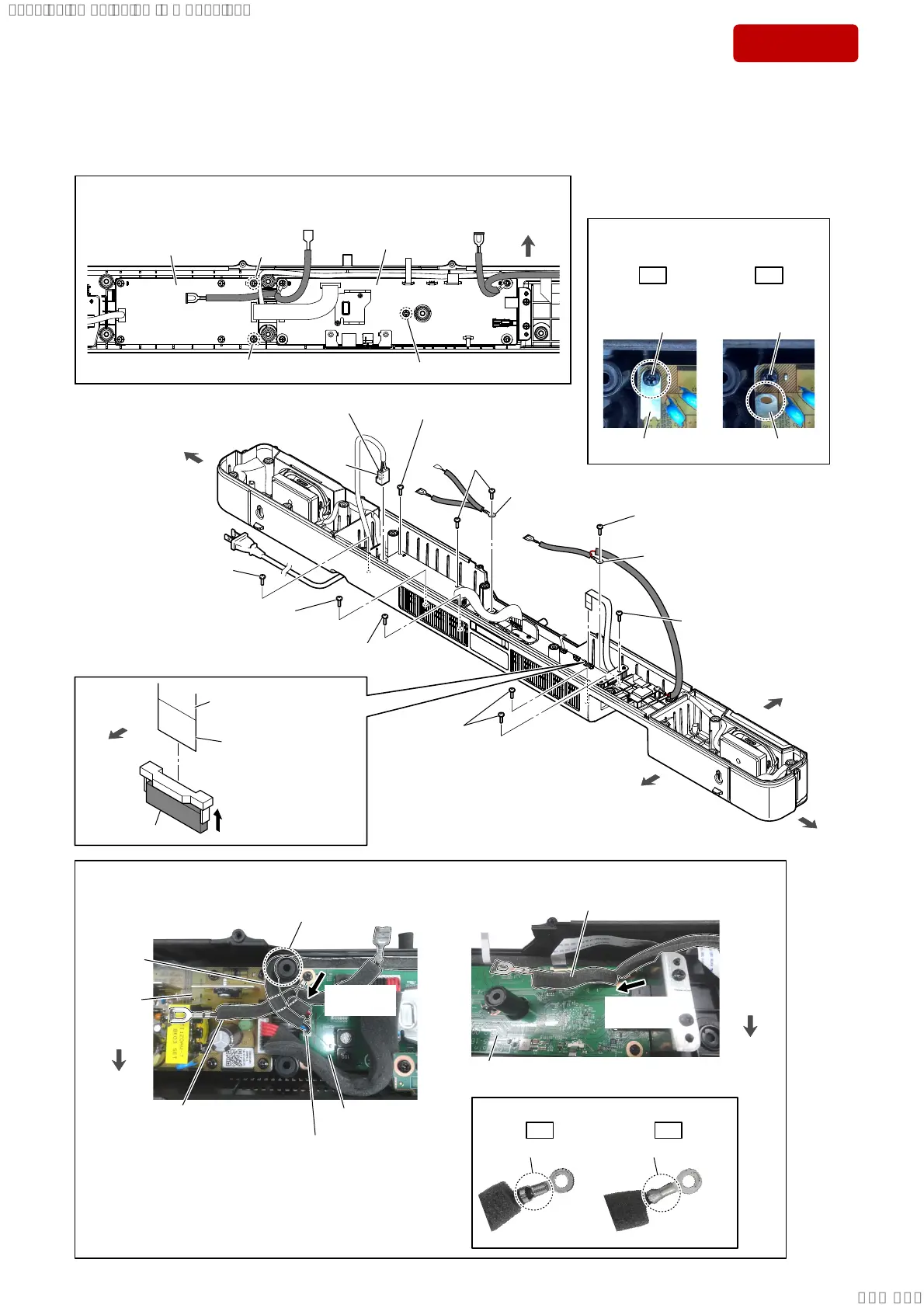
2-11. CHASSIS BLOCK-1
• Continued on 2-12 (page 19).
OK NG
,QVWDOODWLRQGLUHFWLRQIRUWKHOXJWHUPLQDO
–7RSYLHZ–
Caulking is upward. Caulking is downward.
front side
rear side
left side
right side
claw
side
4 screw
(BTP3 u 10)
1
AC cord connector
(CN1)
NRWHVZKHQGLVDVVHPEOLQJWKHFKDVVLVEORFN
Removing the three screws at the
Ÿ
mark screws is not necessary.
Ÿ
Ÿ
–7RSYLHZ–
Ÿ
MAIN board
POWER board
front side
2
Unlock the
connector.
connector (CN4)
terminal
side
3 Draw the FFC (18 core)
out of the connector.
rear side
4 screw
(BTP3 u 10)
4 screw
(BTP3 u 10)
4 two screws
(BTP3 u 10)
4 screw (BTP3 u 10)
(See Fig. G)
4 screw
(BTP3 u 10)
5 wire with lug terminal
(See Fig. F)
5 wire with lug terminal
(See Fig. E)
4 two screws
(BTP3 u 10)
)LJG!
NRWHDERXWLQVWDOOLQJWKHVFUHZ
:LUHZLWKOXJWHUPLQDOVHWWLQJ
lug terminal
direction
wire with
lug terminal
wire with lug terminal
MAIN board
MAIN board
rear side
rear side
)LJ)!)LJ(!
–7RSYLHZ–
–7RSYLHZ–
OK NG
GND plate
GND plate
screwscrew
GND plate is
screwed.
GND plate is
floating.
–7RSYLHZ–
lug terminal
direction
4 screw
(BTP3 u 10)
connector
(CN3)
speaker
cable
POWER
board
Pass the speaker cable
beside the screw boss.
SYSSET
2019/02/1301:27:25(GMT+09:00)
 Loading...