XAV-AX150
22
Sony CONFIDENTIAL
For Authorized Servicer
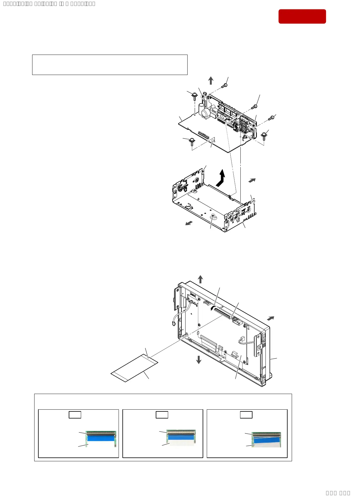
3-5. MAIN BOARD
1 screw
(PTT2.6 u 6)
front side
rear side
1 screw
(PTT2.6 u 6)
1 screw
(PTT2.6 u 6)
2 ground point screw
(PTT2.6 u 6)
chassis block
5 MAIN board
(See Note 1)
Note 2:
When installing the MAIN board,
align the rib and two bosses with
the three holes.
rib
hole
2 ground point screw
(PTT2.6 u 6)
2 ground point screw
(PTT2.6 u 6)
4
top side
3 boss
3 boss
hole
hole
Note 1:
When the MAIN board is replaced, be sure to refer the “IMPORTANT
NOTE FOR REPLACING THE MAIN BOARD OR IC801 ON THE
MAIN BOARD” on page 4, and perform it.
3-6. FLEXIBLE FLAT CABLE (60 CORE)
top side
front side
bottom side
front panel block
Insert is straight to the interior.
OK
Connector is unlock. Insert at a slant.
Note:
When installing the flexible flat cable (60 core) to the connector (CN1102) on the DISPLAY board,
insert straight to the connector and lock a connector completely. No slanting after insertion.
NG
flexible flat cable
(60 core)
flexible flat cable
(60 core)
flexible flat cable
(60 core)
connector
connector
NG
connector
2 flexible flat cable (60 core)
(See Note)
The opposite side
is terminal side.
1 Unlock.
connector
(CN1102)
DISPLAY
board
SYSSET
2020/02/0723:51:10(GMT+09:00)
 Loading...