XAV-AX150
25
Sony CONFIDENTIAL
For Authorized Servicer
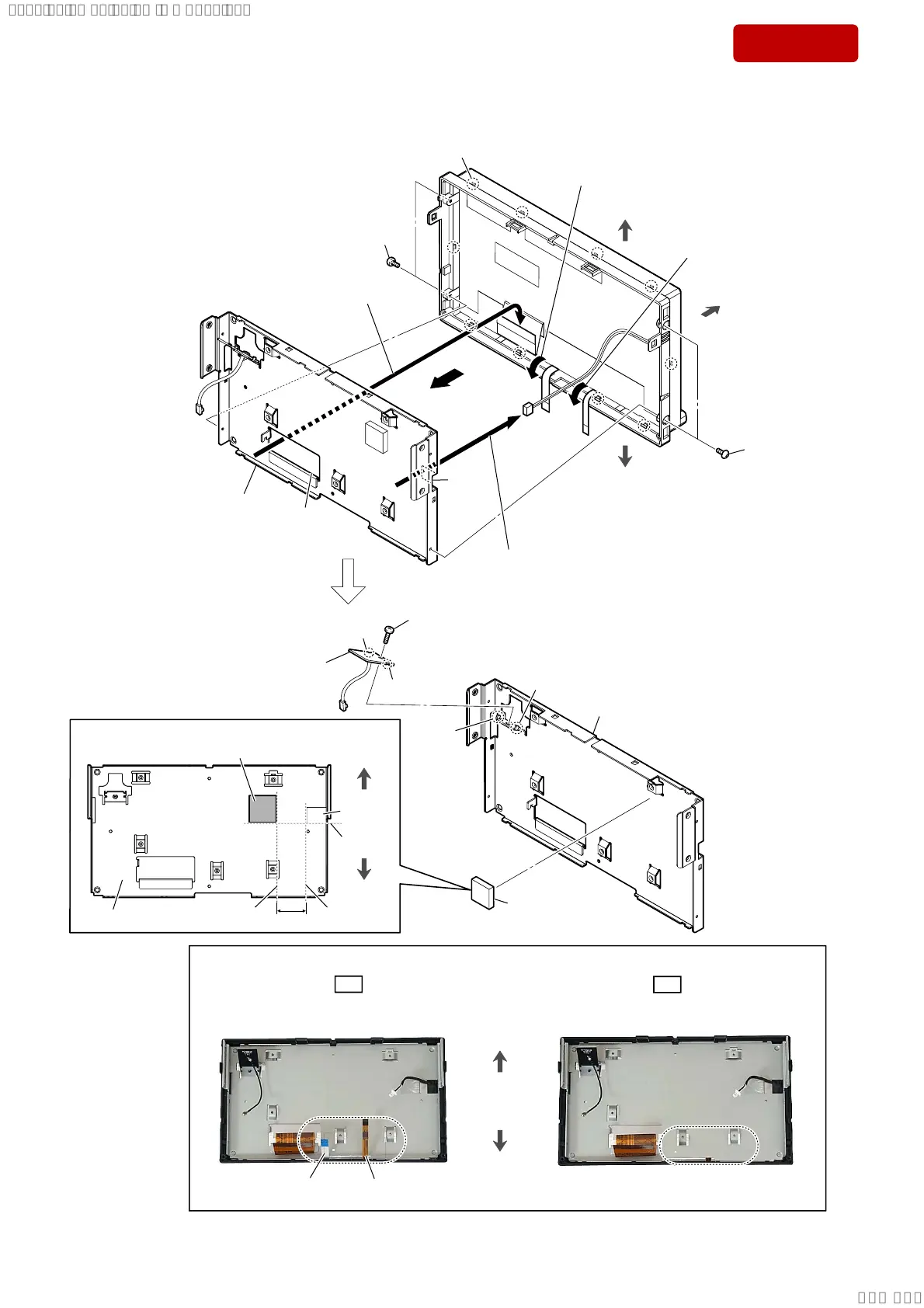
3-9. BT ANTENNA
7 Draw the LCD wire out of
the hole in
chassis
display
.
1 two screws
(Z S1.7 u 4)
front side
top side
bottom side
1 two screws
(Z S1.7 u 4)
4 total ten claws
6 Draw the LCD FPC out of
the hole in
chassis
display
.
8 chassis display
block
(See Fig. B)
qs
chassis display
q; screw
(2 u 4) (black)
qa
rib
qa
rib
groove
groove
qd BT antenna
Note:
When installing the BT antenna,
align the two ribs and two grooves.
3 Move the touch panel FPC
to the outer side.
2 Move the flexible flat cable
(10 core) to the outer side.
OK
NG
1RWHDERXWLQVWDOOLQJWKHFKDVVLVGLVSOD\EORFN
Touch panel FPC and flexible flat cable (10 core)
are visible.
Touch panel FPC and flexible flat cable (10 core)
are not visible.
flexible flat cable
(10 core)
touch panel FPC
top side
bottom side
5
)LJ%!
9 sheet heat transfer
sheet heat transfer
21.5 mm
3DVWLQJSRVLWLRQRIWKHVKHHWKHDWWUDQVIHU
chassis display
top side
bottom side
guide line
guide lineguide line
hole
hole
hole
SYSSET
2020/02/0723:51:10(GMT+09:00)
 Loading...