STLINK-V3SET functional description UM2448
22/49 UM2448 Rev 6
For details regarding baud rates, refer to Section 14.2.
Bridge GPIOs
Four GPIO signals are available on MB1440 CN8 and CN9. Basic management is provided
by the public ST bridge software interface.
7.3.6 LEDs
PWR LED: red light indicates that 5 V is enabled (only used when a daughterboard is
plugged).
COM LED: refer to the technical note Overview of ST-LINK derivatives (TN1235) for details.
7.4 Jumper configuration
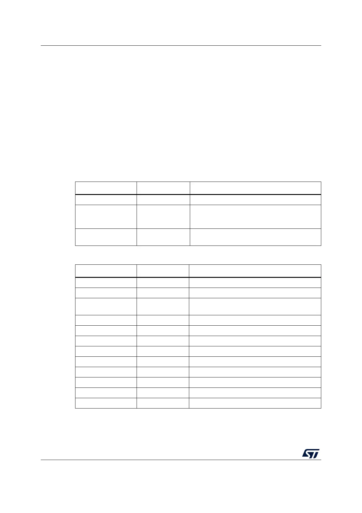
Table 3. MB1441 jumper configuration
Jumper State Description
JP1 ON JTAG clock loopback done on board
JP2 ON
Provides 5 V power on connectors, required for
SWIM usage, B-STLINK-VOLT, and
B-STLINK-ISOL boards.
JP3 OFF
STLINK-V3SET reset. Can be used to enforce
STLINK-V3SET UsbLoader mode
Table 4. MB1440 jumper configuration
Jumper State Description
JP1 Not used GND
JP2 Not used GND
JP3 ON
Getting 5 V power from CN12, required for SWIM
usage.
JP4 OFF Disables SWIM input
JP5 ON JTAG clock loopback done on board
JP6 OFF Disables SWIM output
JP7 OFF Closed to use CAN through CN5
JP8 ON Provides 5 V power to CN7 (internal use)
JP9 ON Provides 5 V power to CN10 (internal use)
JP10 OFF Closed to enable I
2
C pull-ups
JP11 Not used GND
JP12 Not used GND
 Loading...


