Board connectors UM2448
24/49 UM2448 Rev 6
8.1.2 STDC14 (STM32 JTAG/SWD and VCP)
The STDC14 CN1 connector allows the connection to an STM32 target using the JTAG or
SWD protocol, respecting (from pin 3 to pin 12) the ARM10 pinout (Arm Cortex debug
connector). But it also advantageously provides two UART signals for the Virtual COM port.
The related pinout for the STDC14 connector is listed in
Table 6.
The used connector is SAMTEC FTSH-107-01-L-DV-K-A.
8.2 Connectors on MB1440 board
8.2.1 STDC14 (STM32 JTAG/SWD and VCP)
The STDC14 CN1 connector on MB1440 replicates the STDC14 CN1 connector from the
MB1441 main module. Refer to
Section 8.1.2 for details.
8.2.2 Legacy Arm 20-pin JTAG/SWD IDC connector
The CN2 connector allows the connection to an STM32 target in the JTAG or SWD mode.
Its pinout is listed in
Table 7. It is compatible with the pinout of ST-LINK/V2, but the STLINK-
V3SET does not manage the JTAG TRST signal (pin 3).
4ID -
5GND GND
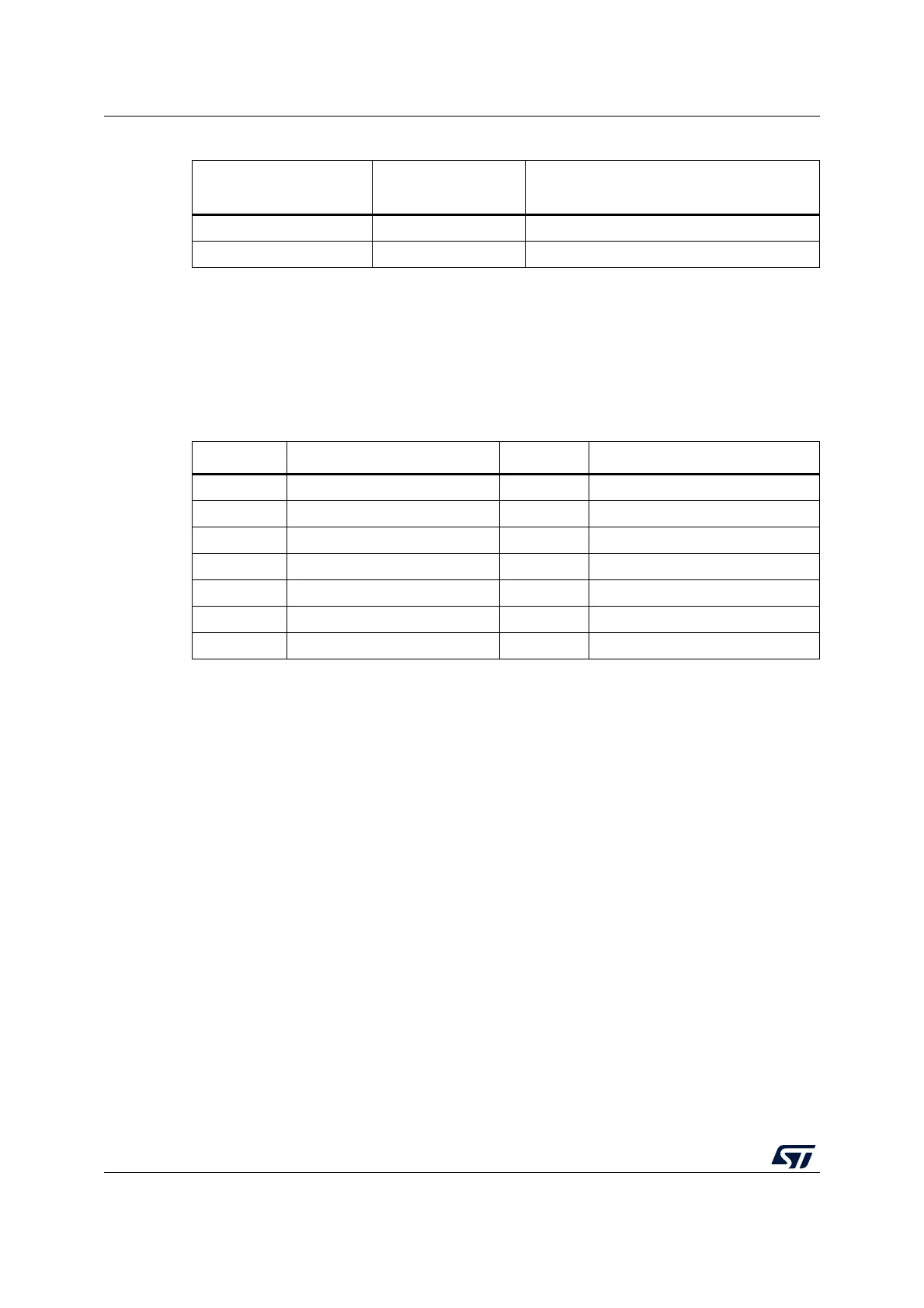
Table 5. USB Micro-B connector pinout CN5 (continued)
Pin
number
Pin
name
Function
Table 6. STDC14 connector pinout CN1
Pin No. Description Pin No. Description
1 Reserved
(1)
1. Do not connect to the target.
2 Reserved
(1)
3T_VCC
(2)
2. Input for STLINK-V3SET.
4 T_JTMS/T_SWDIO
5 GND 6 T_JCLK/T_SWCLK
7GND8T_JTDO/T_SWO
(3)
3. SWO is optional, required only for Serial Wire Viewer (SWV) trace.
9 T_JRCLK
(4)
/NC
(5)
4. Optional loopback of T_JCLK on the target side, required if loopback removed on the STLINK-V3SET side.
5. NC means not required for the SWD connection.
10 T_JTDI/NC
(5)
11 GNDDetect
(6)
6. Tied to GND by STLINK-V3SET firmware; may be used by the target for detection of the tool.
12 T_NRST
13 T_VCP_RX
(7)
7. Output for STLINK-V3SET
14 T_VCP_TX
(2)
 Loading...


