UM2448 Rev 6 23/49
UM2448 Board connectors
48
8 Board connectors
11 user connectors are implemented on the STLINK-V3SET product and are described in
this paragraph:
• 2 user connectors are available on the MB1441 board:
– CN1: STDC14 (STM32 JTAG/SWD and VCP)
– CN5: USB Micro-B (connection to the host)
• 9 user connectors are available on the MB1440 board:
– CN1: STDC14 (STM32 JTAG/SWD and VCP)
– CN2: Legacy Arm 20-pin JTAG/SWD IDC connector
–CN3: VCP
– CN4: SWIM
– CN5: bridge CAN
–CN6: SWD
– CN7, CN8, CN9: bridge
Other connectors are reserved for internal use and are not described here.
8.1 Connectors on MB1441 board
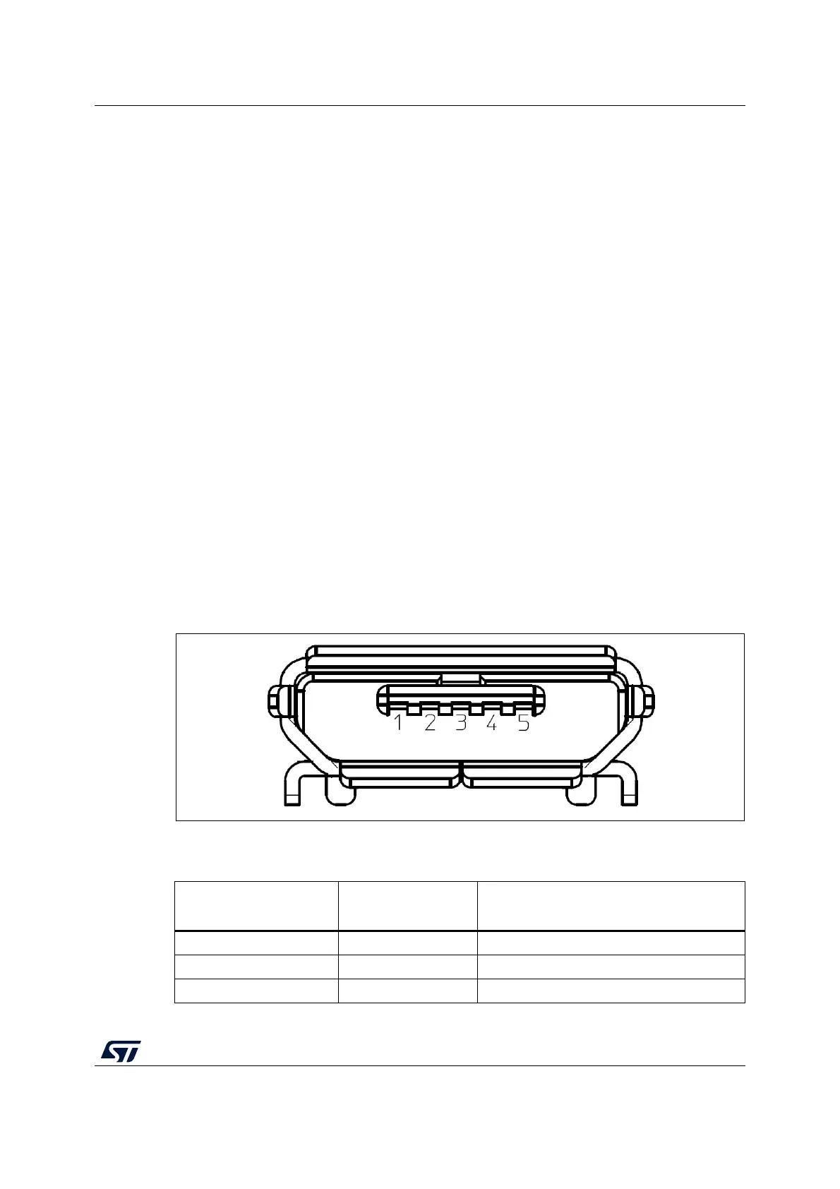
8.1.1 USB Micro-B
The USB connector CN5 is used to connect the embedded STLINK-V3SET to the PC.
Figure 14. USB Micro-B connector CN5 (front view)
The related pinout for the USB ST-LINK connector is listed in Table 5.
Table 5. USB Micro-B connector pinout CN5
Pin
number
Pin
name
Function
1 VBUS 5 V power
2 DM (D-) USB differential pair M
3 DP (D+) USB differential pair P
 Loading...


