EasyManua.ls Logo

ST STLINK-V3SET User Manual

ST STLINK-V3SET
49 pages
To Next Page IconTo Next Page
To Previous Page IconTo Previous Page
Page #7 background image
UM2448 Rev 6 7/49
UM2448 List of figures
7
List of figures
Figure 1. STLINK-V3SET product top view . . . . . . . . . . . . . . . . . . . . . . . . . . . . . . . . . . . . . . . . . . . . . 1
Figure 2. Probe top side. . . . . . . . . . . . . . . . . . . . . . . . . . . . . . . . . . . . . . . . . . . . . . . . . . . . . . . . . . . 12
Figure 3. Connections . . . . . . . . . . . . . . . . . . . . . . . . . . . . . . . . . . . . . . . . . . . . . . . . . . . . . . . . . . . . 13
Figure 4. Probe with adapter . . . . . . . . . . . . . . . . . . . . . . . . . . . . . . . . . . . . . . . . . . . . . . . . . . . . . . . 13
Figure 5. Operating mode to change the configuration . . . . . . . . . . . . . . . . . . . . . . . . . . . . . . . . . . . 14
Figure 6. Hardware board MB1441 . . . . . . . . . . . . . . . . . . . . . . . . . . . . . . . . . . . . . . . . . . . . . . . . . . 15
Figure 7. Hardware board MB1440 . . . . . . . . . . . . . . . . . . . . . . . . . . . . . . . . . . . . . . . . . . . . . . . . . . 16
Figure 8. MB1441 top layout . . . . . . . . . . . . . . . . . . . . . . . . . . . . . . . . . . . . . . . . . . . . . . . . . . . . . . . 17
Figure 9. MB1441 bottom layout . . . . . . . . . . . . . . . . . . . . . . . . . . . . . . . . . . . . . . . . . . . . . . . . . . . . 17
Figure 10. MB1440 top layout . . . . . . . . . . . . . . . . . . . . . . . . . . . . . . . . . . . . . . . . . . . . . . . . . . . . . . . 18
Figure 11. MB1441 mechanical drawing . . . . . . . . . . . . . . . . . . . . . . . . . . . . . . . . . . . . . . . . . . . . . . . 18
Figure 12. MB1440 mechanical drawing . . . . . . . . . . . . . . . . . . . . . . . . . . . . . . . . . . . . . . . . . . . . . . . 19
Figure 13. Firmware selection for a second Virtual COM port . . . . . . . . . . . . . . . . . . . . . . . . . . . . . . . 21
Figure 14. USB Micro-B connector CN5 (front view) . . . . . . . . . . . . . . . . . . . . . . . . . . . . . . . . . . . . . . 23
Figure 15. MB1441 mechanical dimensions (in millimeters) . . . . . . . . . . . . . . . . . . . . . . . . . . . . . . . . 30
Figure 16. Closed casing for STM32 debug with B-STLINK-VOLT . . . . . . . . . . . . . . . . . . . . . . . . . . . 34
Figure 17. Opened casing for access to all connectors with B-STLINK-VOLT . . . . . . . . . . . . . . . . . . 36
Figure 18. B-STLINK-VOLT . . . . . . . . . . . . . . . . . . . . . . . . . . . . . . . . . . . . . . . . . . . . . . . . . . . . . . . . . 37
Figure 19. Closed casing for STM32 debug with B-STLINK-ISOL. . . . . . . . . . . . . . . . . . . . . . . . . . . . 40
Figure 20. Opened casing for access to all connectors with B-STLINK-ISOL . . . . . . . . . . . . . . . . . . . 42

Table of Contents

Question and Answer IconNeed help?

Do you have a question about the ST STLINK-V3SET and is the answer not in the manual?

ST STLINK-V3SET Specifications

General IconGeneral
BrandST
ModelSTLINK-V3SET
CategoryMotherboard
LanguageEnglish

Summary

Introduction

Features

General Information

Ordering Information

Development Environment

System Requirements

Lists the required operating systems and hardware for the STLINK-V3SET.

Development Toolchains

Specifies the supported software development tools and IDEs for the STLINK-V3SET.

Conventions

Quick Start

STLINK-V3SET Functional Description

STLINK-V3SET Overview

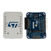
Provides a general overview of the STLINK-V3SET debugger/programmer, its features and capabilities.

Hardware Layout

Details the hardware components and layout of the STLINK-V3SET main module (MB1441).

STLINK-V3SET Functions

Details the various functions and protocols supported by the STLINK-V3SET.

Board Connectors

Connectors on MB1441 Board

Details the user connectors available on the MB1441 board, including USB Micro-B and STDC14.

Connectors on MB1440 Board

Details the 9 user connectors available on the MB1440 board for various communication protocols.

Flat Ribbons

Mechanical Information

Software Configuration

Supporting Toolchains (not exhaustive)

Lists the toolchain versions that support the STLINK-V3SET, including minimum required versions.

Drivers and Firmware Upgrade

Explains the need for driver installation and firmware updates for the STLINK-V3SET.

STLINK-V3SET Frequency Selection

Describes the different operating frequencies for the STLINK-V3SET and their implications.

Mass Storage Interface

Details the virtual mass storage interface for drag-and-drop programming of STM32 flash memory.

Bridge Interface

Explains the USB interface for bridging functions to STM32 target protocols like SPI, I2C, CAN, UART, and GPIOs.

B-STLINK-VOLT Board Extension Description

B-STLINK-VOLT Features

Highlights the key features of the B-STLINK-VOLT voltage adapter board for the STLINK-V3SET.

B-STLINK-VOLT Connection Instructions

Provides step-by-step guides for connecting the B-STLINK-VOLT board with the STLINK-V3SET.

B-STLINK-VOLT Closed Casing for STM32 Debug

Instructions for assembling the STLINK-V3SET with B-STLINK-VOLT in a closed casing.

B-STLINK-VOLT Opened Casing for All Connectors

Instructions for assembling the STLINK-V3SET with B-STLINK-VOLT using the MB1440 adapter.

B-STLINK-VOLT Bridge GPIO Direction

Explains how to manually configure the direction of bridge GPIO signals on the B-STLINK-VOLT board.

B-STLINK-VOLT Jumper Configuration

Details the jumper settings on the MB1441 main module when using the B-STLINK-VOLT board.

B-STLINK-VOLT Target Voltage Connection

Specifies how to provide target voltage to the B-STLINK-VOLT board for proper operation.

B-STLINK-VOLT Board Connectors

Describes the connectors on the B-STLINK-VOLT board (MB1598) and their relation to other boards.

B-STLINK-ISOL Board Extension Description

B-STLINK-ISOL Features

Highlights the features of the B-STLINK-ISOL voltage adapter and galvanic isolation board.

B-STLINK-ISOL Connection Instructions

Provides step-by-step guides for connecting the B-STLINK-ISOL board with the STLINK-V3SET.

B-STLINK-ISOL Closed Casing for STM32 Debug

Instructions for assembling the STLINK-V3SET with B-STLINK-ISOL in a closed casing.

B-STLINK-ISOL Opened Casing for All Connectors

Instructions for assembling the STLINK-V3SET with B-STLINK-ISOL using the MB1440 adapter.

B-STLINK-ISOL Bridge GPIO Direction

Explains the fixed hardware direction of bridge GPIO signals on the B-STLINK-ISOL board.

B-STLINK-ISOL Jumper Configuration

Details the jumper settings on the B-STLINK-ISOL board (MB1599) for JTAG clock path configuration.

B-STLINK-ISOL Target Voltage Connection

Specifies how to provide target voltage to the B-STLINK-ISOL board for proper operation.

B-STLINK-ISOL Board Connectors

Describes the connectors on the B-STLINK-ISOL board (MB1599) and their relation to other boards.

Performance Figures

Global Overview

Provides an overview of achievable maximal performances with STLINK-V3SET on different communication channels.

Baud Rate Computing

Explains how to compute baud rates for VCP and SWV interfaces aligning with target baud rates.

STLINK-V3SET, B-STLINK-VOLT, and B-STLINK-ISOL Information

Product Marking

Describes the stickers on the PCB providing product order code, identification, and revision information.

STLINK-V3SET Product History

Details the product identification and limitations for the STLINK-V3SET.

B-STLINK-VOLT Product History

Details the product identification and limitations for the B-STLINK-VOLT board.

B-STLINK-ISOL Product History

Details the product identification and limitations for the B-STLINK-ISOL board.

Board Revision History

Lists the revision history for the MB1441, MB1440, MB1598, and MB1599 boards.

Appendix A Federal Communications Commission (FCC)

FCC Compliance Statement

Provides FCC compliance statements, including Part 15.19, 15.21, and 15.105 regulations.

Revision History

Related product manuals