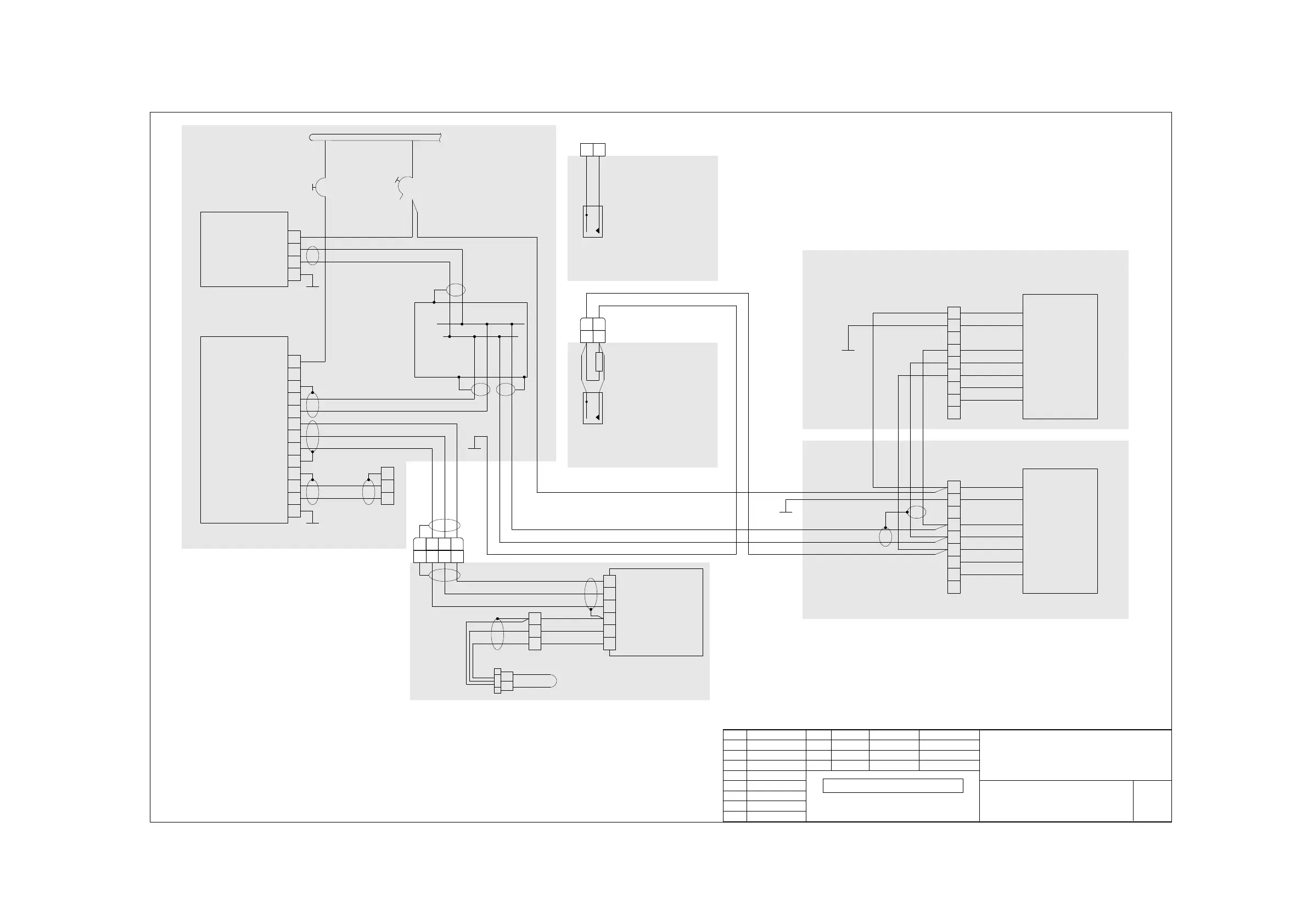
I S12 MAIN SYSTEM AUTOPILOT
27.03.2017 Gulbe
P308-124913
00
DE.21G.0068 EASA 21J.250
01
Date
Name
checked
drawn
Title
Doc Number
Page
Rev. Change
P069-E074-196
S12 Main System
Autopilot
Related manufacturer's doc:
EFIS D-10A Installation Guide
Dynon P/N 100341-000 Rev. J
Dynon Firmware Version 5.6.1.
CHECK FOR UPDATES BEFORE USING THIS DIAGRAM
All wires AWG22, except power supply and power ground: AWG20
DSAB lines: Twisted pair
RS232 lines: shielded, 2 conductor twisted
RS485 lines: shielded, 3 conductor twisted
6
5
9
7
2
1
EDC-D10A
(female D9)
OAT Probe
Data B
PWR
Data A
Data GND
blue
yellow
red
3
2
1
Molex
3pol
AVIONICS BUS - INSTRUMENT PANEL
red
black
green
blue
yellow
wht-grn
wht-blu
Power 10-30V DC
GND
DSAB-A
DSAB-B
Disengage
(spare)
(spare)
red
black
green
blue
yellow
wht-grn
wht-blu
Power 10-30V DC
GND
DSAB-A
DSAB-B
Disengage
(spare)
(spare)
1
2
3
4
5
6
7
8
9
1
2
3
4
5
6
7
8
9
Roll
SERVO
Pitch
SERVO
SC
5k
5
2
3
9
22
10
Serial 1 GND
Serial 1 TX
Serial 1 RX
female
Sub-D-9
black
white
RS232 to PC
11
24
23
12
EDC-D10A TX
Switched Power Out 16.8V
EDC-D10A RX
EDC-D10A GND
AP14Pb
AP14Pw
AP14Pr
4
5
16
DSAB A
DSAB B
GND
black
white
5A EFIS
DSAB A
DSAB B
2 A Autopilot
Power 10-30V DC
GND
Master Power +13,75V
1
18
Audio Out
DSAB
Coupler
EFIS D-10A
AP74
3
Master GND
AP1P
AP2P
AP3F
AP3FN
AP2FN
4
3
16
17
AP10Pb
AP10Pw
AP10Ps
AP11Fw
AP11Fb
AP12F
AP13F
AP13PN
DSAB Master
white
black
white
black
AP14Ps
AP14Ps
refer to: P308-124.910
S12 Main System -
DC Generation
Left Stick:
Connect PTT as
AP Disengage
Connect SC as PTT
Instrument Panel
L/H Control Linkage Comp.
L/H Inner Wing
Center Airframe
Tail Boom Comp.
27.03.2017 Baum
CPC
9pol
CPC
9pol
CPC
16pol
11 121314
11 121314
CPC
16pol
11 12
AP20P
AP20PN
AP4P
AP4PN
11 12
1 x 831.332
AP Disengage
R/H Control Linkage Comp.
CPC
16pol
11 12
Right Stick:
Prepare wires for
AP Disengage
in copilot stick
connector
01
P061-2017-039
 Loading...

