DOCUMENT NUMBER:
L500-912.820 ISSUE JUL 20, 2016
AMENDMENT: 00
DATE:
CHAPTERPAGE 347
MAINTENANCE MANUAL STEMME S12
3.7.7.3 SEMICONDUCTOR SWITCH BOX
An 8-channel MOSFET-based switch box is installed to control the power for fuel pumps, lights
and variable pitch propeller. The use of semiconductors improves the system reliability, reduces
electromagnetic emissions and saves weight and space. The switch box is located close to the
batteries and to the distribution boxes.
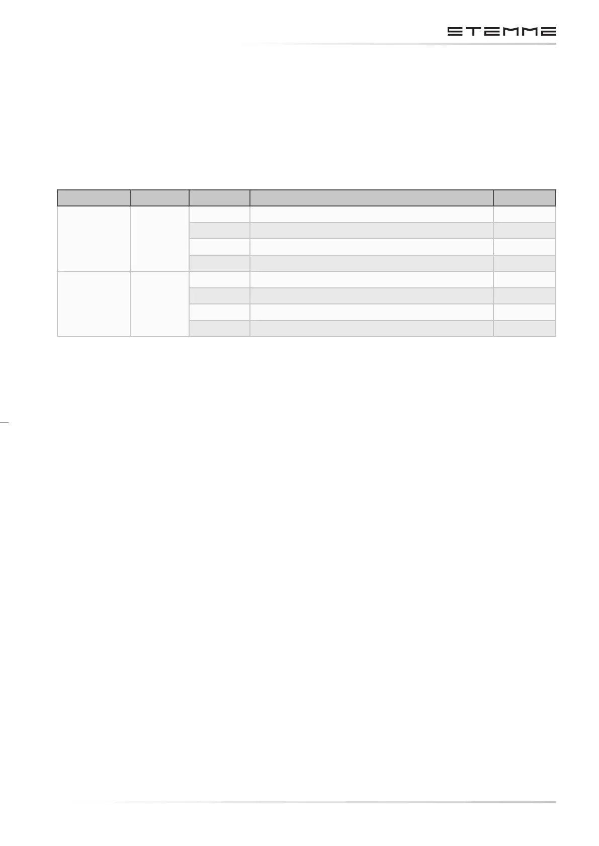
The box includes 8 channels with a switching capacity of max. 36 A each.
Connector System Channel # Function Fuse
Gray Main
1 Position lights 5 A
2 Anti-Collision Lights 5 A
3 Landing Light 5 A
4 Auxiliary Fuel Pump 5 A
Black Engine
1 -spare-
2 Propeller Pitch Control 15 A
3 Transfer Pump Left Wing 5 A
4 Transfer Pump Right Wing 5 A
3.7.8 MAIN SYSTEM DISTRIBUTION BOX
4.7.8 Main System Distribution Box
This box includes a metallic bus bar to which the main system battery and the alternator are
connected via master fuses. The main system master relay and a number of fuses are located in
a combined fuse-relay-holder. The box is made of plastic with a sealed cover and is mounted on
a rack on the aft area of upper re wall.
3.7.9 ENGINE SYSTEM DISTRIBUTION BOX
This box includes a metallic bus bar to which the engine system battery, the starter, the generator
and the external power supply are connected via master fuses. The engine system master relay
and a number of fuses are located in a combined fuse-relay-holder. The box is made of plastic
with a sealed cover and is mounted on a rack on the aft area of upper re wall.
3.7.10 TCU BOARD
The following elements of engine control are located on this board:
• The turbocharger control unit TCU.
• The waste gate servo.
• The ambient pressure sensor.
• The starter relay.
• The voltage regulator of the internal generator.
• The power relay for the ground power supply.
 Loading...

