DOCUMENT NUMBER:
L500-912.820 ISSUE JUL 20, 2016
AMENDMENT: 00
DATE:
CHAPTERPAGE 349
MAINTENANCE MANUAL STEMME S12
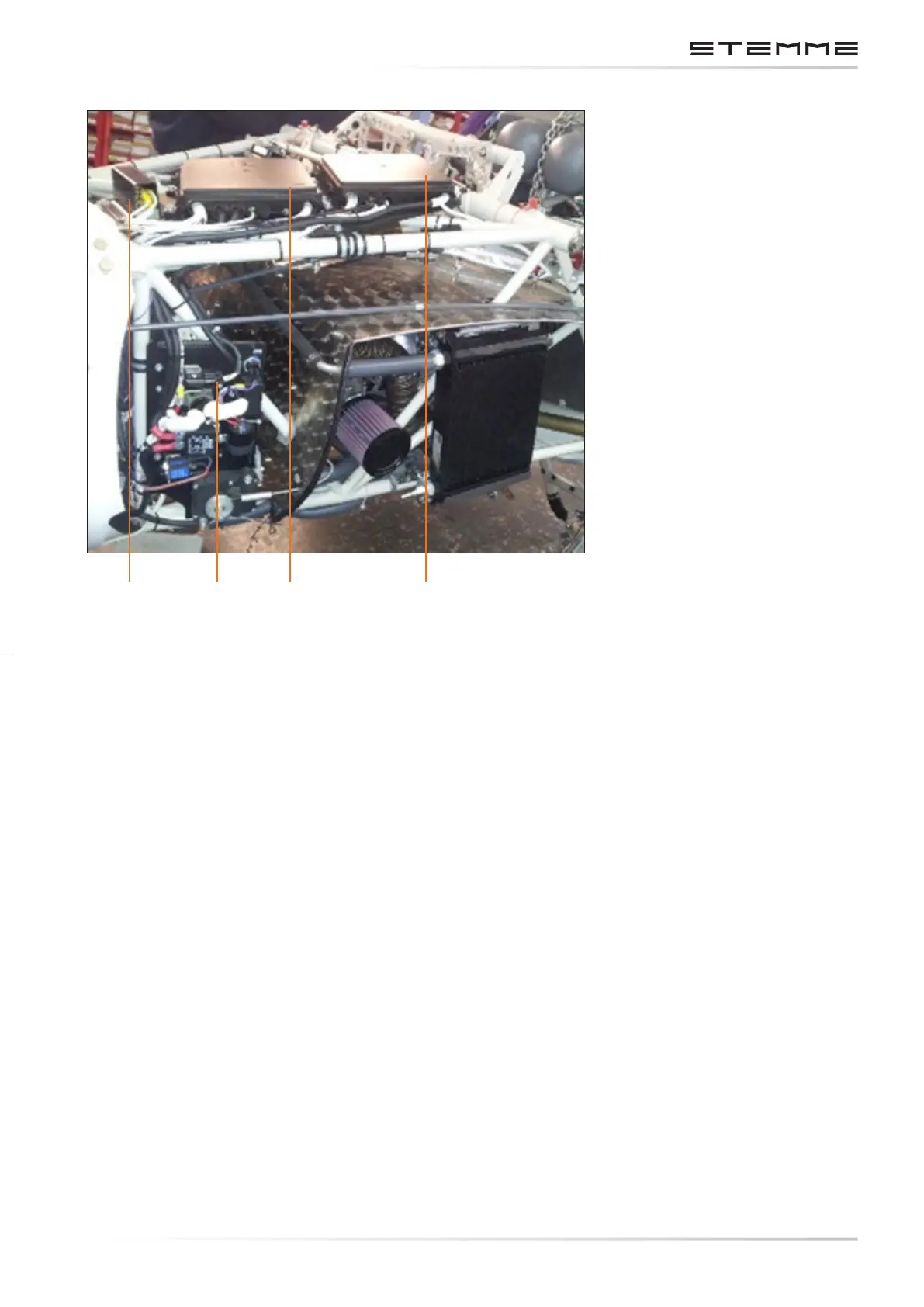
2. Shunts
3. Engine System Box
4. Main System Box
5. TCU Box
Figure 3.7.b
Electrical Components Center Fuselage
3.7.11 INSTRUMENT PANEL BUS SYSTEM
Two fuse holders, one for each system, are located behind the instrument panel. Each fuse holder
forms a distribution bus. See chapter 7.3.1 and 7.3.2 for a list of the connected devices on
each bus.
From the main system bus a wire leads to the group of circuit breakers on the instrument
panel front. These circuit breakers form the avionics bus. Radio communication and navigation
equipment is connected here.
All engine monitoring instruments are connected to the engine system bus.
52 3 4
 Loading...

