FLIGHT MANUAL TSA-M, VARIANT S6
Doc.-No.: P400-006.000 E Page: 7-14 Revision: 1
Date of Issue: 07. October 2008 Date of Rev.: 28.01.2011
7.6.2 Control-Elements of the Instrument-Panel
The following illustration shows the layout of the additional control-elements of
the instrument-panel in the standard-configuration.
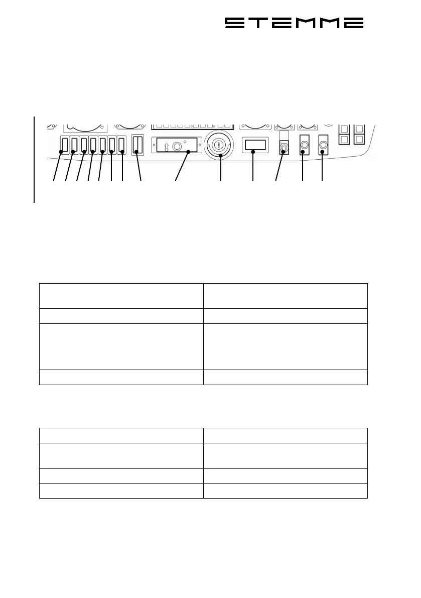
Illustration 7-3: Control-Elements of the Instrument-Panel
Control-elements of the instrument-panel:
(1) Master-Switch (Batt) and Switch for
(5) TCU-Isolation-Switch (red safety-
(2) Control-Unit for Propeller-Pitch
(6) Main Circuit-Breaker 50A
(3) Ignition-Switch (7) Circuit-Breaker for External-
Alternator 50A (see also 7.13.4
Electrical Consumers and Circuit-
(4) Fuel-Pressure-Difference-Gauge
Circuit-breakers/switches of the instrument-panel:
(S2) Fuel-Transfer-Pump (for
(S6) Landing-Light
(S7) Avionics-Master-Switch
(S4) Anti-Collision-Light
S1 S2 S3 S4 S5 S6 S7 1 2 3 4 5 6 7
 Loading...


