EasyManuals Logo
Home>STEMME>Aircrafts>S6

STEMME S6 User Manual

STEMME S6
215 pages
To Next Page IconTo Next Page
To Previous Page IconTo Previous Page
Page #194 background imageLoading...
Page #194 background image
FLIGHT MANUAL TSA-M, VARIANT S6
Doc.-No.: P400-006.000 E Page: 7-39 Revision: 10
Date of Issue: 07. October 2008 Date of Rev.: 06.07.2020
Avionics-Bus: supplies all avionics and is connected to the main-bus with the
„Avionics“-isolation-switch. The avionics-bus is made up of the circuit-breakers
A4 – A10 (Ill. 7-2).
Internal-Generator-Bus: supplies the TCU and the main-fuel-pump
independently from the remaining electrical system. The internal-generator-bus
is designed as a distribution-box with fuses and is located on the control-board
in the engine-compartment (at the rear of the fire-wall).
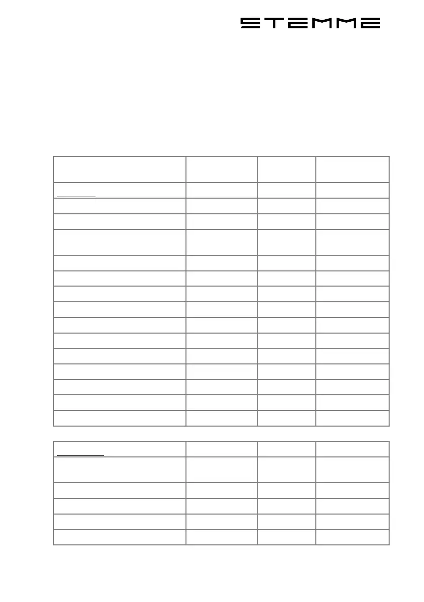
7.13.4 Electrical Consumers and Circuit-Breaker-System
Circuit Circuit-Breaker
(A)
Fuse (A) Isolation-Switch
(A)
Main-Bus
Engine-Bus
10
Master-Circuit-Breaker
50
Circuit-Breaker for the
Alternator
50
Stall-Warning
2
Electrical Trim
5
Propeller-Pitch-Control
5
Voltmeter
2
External-Alternator
5
Instrument-Lighting
5
Position-Lights
10
Anti-Collision-Light
5
Landing-Light
10
Avionics-Isolation-Switch
20
Fire-Warning
3
Engine-Bus
External-Alternator-Warning-
Light
3
Starter-Relay
3
Oil-Press. / CHT L
1
Oil-Temp. / CHT R
1
Low-Fuel-Caution-Light
1

Table of Contents

Other manuals for STEMME S6

Questions and Answers:

Question and Answer IconNeed help?

Do you have a question about the STEMME S6 and is the answer not in the manual?

STEMME S6 Specifications

General IconGeneral
BrandSTEMME
ModelS6
CategoryAircrafts
LanguageEnglish

Related product manuals