35BT 130
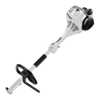
The short circuit wire (2) must be
positioned in the guide under the
ground wire (1).
: Twist the ground wire (1) around
the short circuit wire (2) and pass
it behind flag terminal (3), then
push flag terminal (4) onto the
connector tag (5) so that its
crimped side faces the cylinder.
: Press the ground wire (1) fully
into the guide (arrow).
– Reassemble all other parts in the
reverse sequence.
8.3 Short Circuit Wire on
Control Handle
– Removing and
Installing
– Remove control handle from
handlebar, b 10.1
– Remove the throttle trigger and
lockout lever, b 10.1.1
– Remove the slide control with
torsion spring, b 10.1.2
9912RA141 TG
4
5
13
2
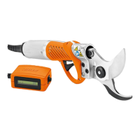
: Take out the screw (1) and
remove the clamp (2).
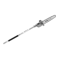
: Remove the microswitch (1).
: Pull out the wiring harness (2)
with throttle cable (3) and
slide (4).
– Remove the throttle cable and
short circuit wire from the engine,
b 8.2
Installing
: Push the microswitch (1) onto the
pins (arrows) as far as stop.
1
2
9912RA163 TG
12 4 3
9912RA164 TG9912RA165 TG
1
Do not twist the wires.
: Push the short circuit wire (1) and
ground wire (2) into the guide
(arrows) – position short circuit
wire under the ground wire.
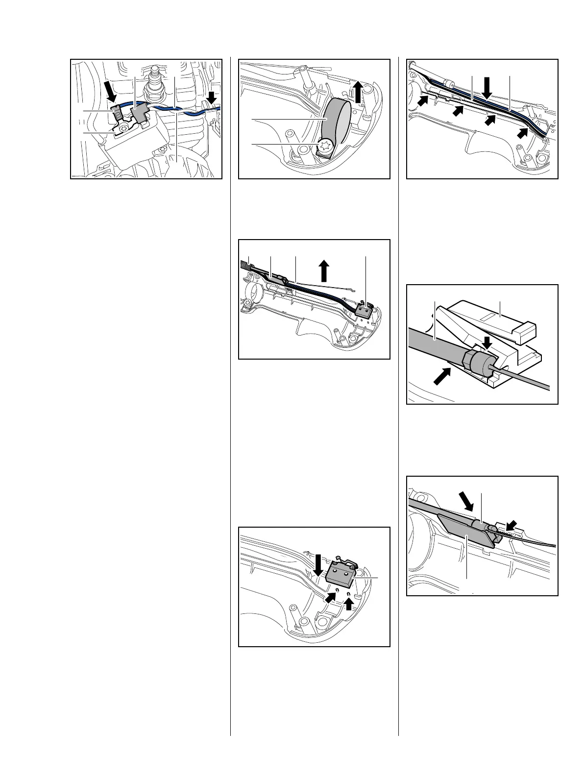
: Push the throttle cable (1) into its
seat (arrow) in the slide (2) until it
snaps into position.
: Push the slide (1) with throttle
cable (2) into the center of the
toothed seat (arrow).
1 2
9912RA166 TG9912RA166 TG
1 2
2
1
9912RA168 TG
 Loading...