45BT 130
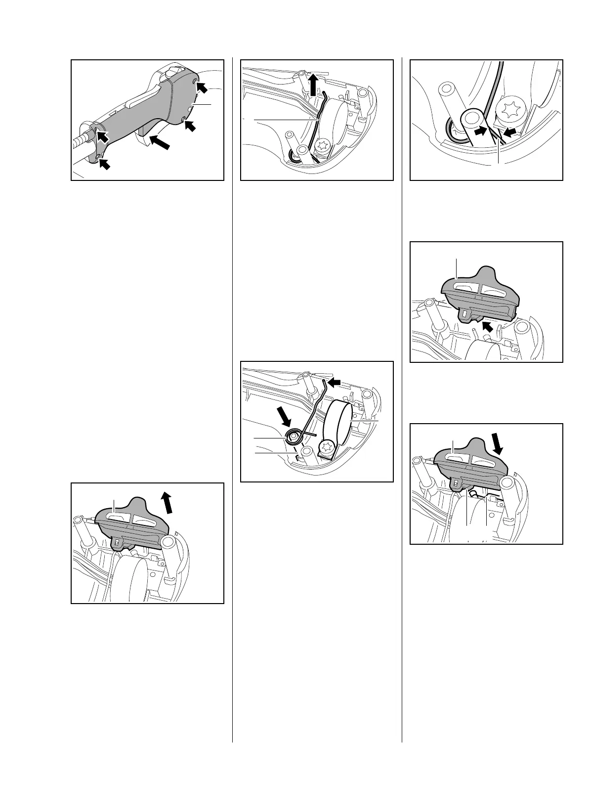
: Fit the handle molding (1), insert
and tighten down the screws
(arrows) firmly – take care not to
pinch the wires between the
handle moldings.
Check operation
The throttle lever must be locked in
position when the lockout lever is
released.
– Check throttle cable adjustment,
re-adjust if necessary, b 10.2
10.1.2 Slide Control
– Remove the handlebar, b 11.1
– Remove the throttle trigger and
lockout lever, b 10.1.1
: Remove the slide control (1).
9912RA277 TG
1
1
9912RA296 TG
: Remove the torsion spring (1)
– Inspect the lockout lever and
torsion spring, replace if
necessary.
– Check the contact spring with
microswitch; replace throttle
cable if necessary, b 8.1,
b 8.2, b 8.3
Installing
: Fit the torsion spring (1) on the
pivot pin (2) so that its bent leg
(arrow) points up and the short
leg is under the clamp (3).
1
9912RA297 TG
1
2
9912RA298 TG
3
: Short leg (1) must be between
the webs (arrows).
: Hold the slide control (1) so that
the cam (arrow) faces down.
: Fit the slide control (1) so that the
peg (2) does not press against
the contact spring (3).
1
9912RA299 TG
1
9912RA300 TG
1
9912RA301 TG
32
 Loading...