42 BT 130
10. Control Levers
10.1 Control Handle
– Removing and
Installing
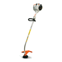
The control handle (1) with slide
control (arrow) is pushed directly
onto the handlebar and secured
with clamps.
To replace the complete control
handle (1), first remove the throttle
cable from the engine, b 8.2.
– Remove control handle from
handlebar, b 11.1
: Unscrew the locknut (1) and take
out the screw (2)
– always install a new locknut.
: Pull the elbow (3) out of the
handlebar (4).
1
9912RA271 TG
3
4
1
9912RA272 TG
: Loosen clamp screws (1) and
pull out the handlebar (2).
– Check the control levers and
replace if necessary,
throttle trigger and lockout lever,
b 10.1.1,
slide control, b 10.1.2
– Inspect throttle cable or short
circuit wire; replace throttle cable
if necessary, b 8.1, b 8.2,
b 8.3
Installing
: Push the handlebar (1) into the
control handle while turning it to
and fro and position it so that the
elbow (arrow) is at right angles to
the control levers.
1
1
9912RA273 TG
2
9912RA274 TG
1
To guarantee the security of the
control handle the clamps must
locate on the knurled areas of the
handlebar – this also ensures that
the control handle is correctly
positioned.
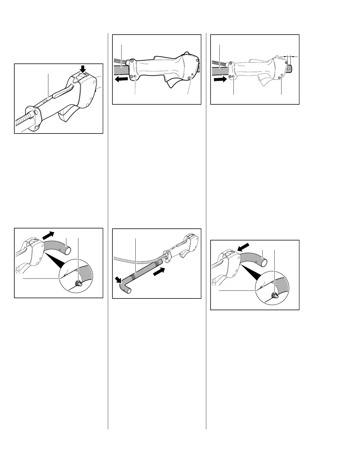
: Continue pushing the
handlebar (1) until it projects 13
mm (a) at the other end – the
clamps are now on the knurled
areas of the handlebar.
: Check the position of the
handlebar, adjust if necessary
and tighten down the clamp
screws (2) firmly.
: Push the elbow (1) into the
handlebar (2), then insert
screw (3) from outboard side.
: Fit new locknut (4) and tighten it
down firmly.
– Mount the control handle with
handlebar, b 11.1
a
1
2 2
9912RA275 TG
1
9912RA276 TG
2
4
3
 Loading...