48 BT 130
11. Handlebar / Handle Frame
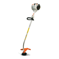
11.1 Handle Tubes
Shown without engine for greater
clarity.
: Unscrew the locknuts (1) and
take out the screws (2)
– always install new locknuts.
: Pull out the handle tubes (3, 4).
9912RA311 TG
2
1
4
3
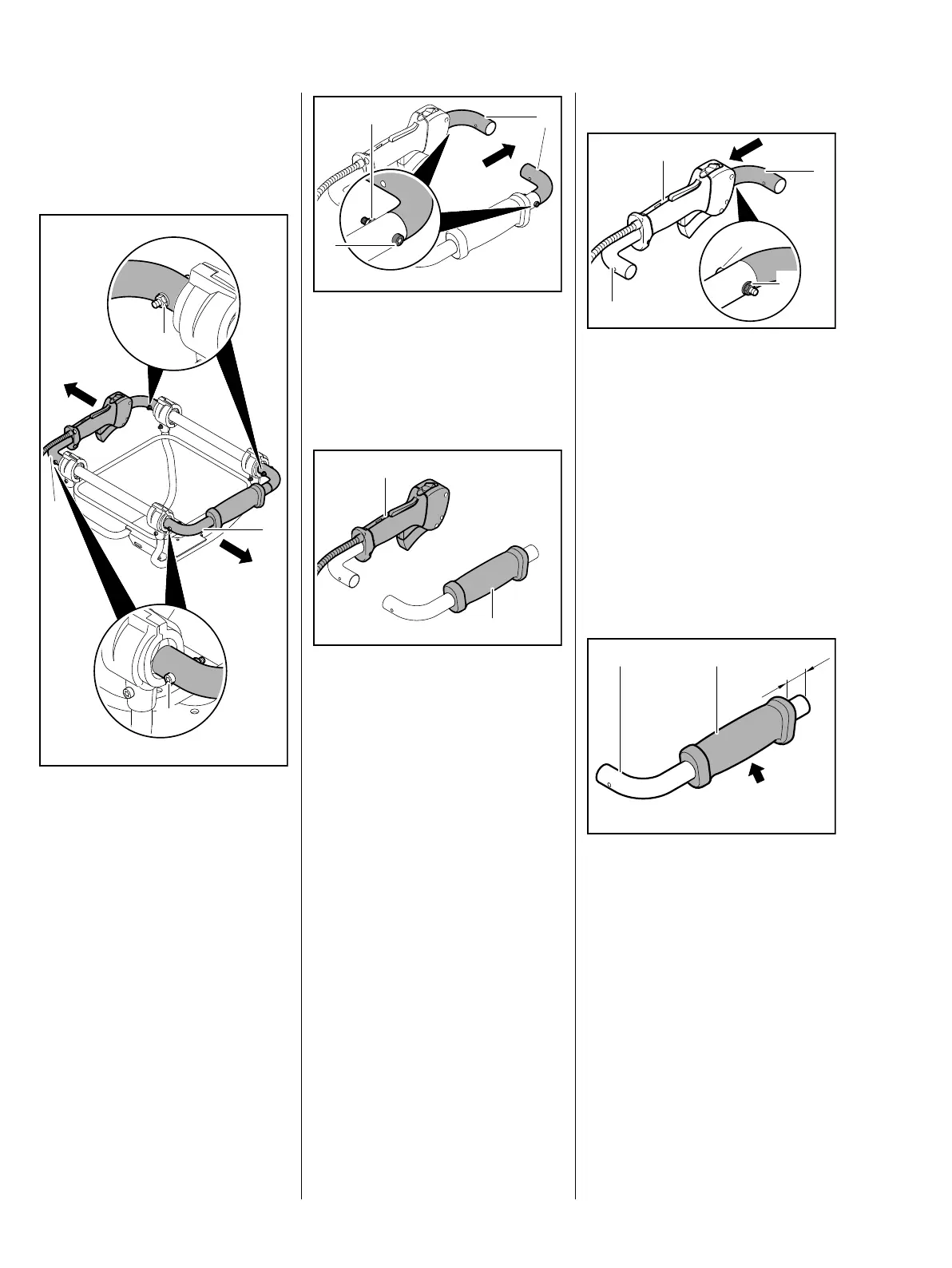
: Unscrew the locknuts (1) and
take out the screws (2)
– always install new locknuts.
: Pull out the elbows (3).
: Remove the control handle (1),
b 10.1
: Inspect the handle (2), cut it open
and remove if necessary.
– Check the handlebars and
elbows and replace if necessary.
– Check the tubes and AV
elements, replace if necessary,
b 9.1
9912RA312 TG
1
2
3
1
9912RA313 TG
2
Installing
: Fit control handle (1) on
handlebar (2) at shroud side,
b 10.1
: Push home the elbow (3) so that
the holes are in alignment.
: Insert screw (4) from outboard
side, fit new locknut (5) and
tighten it down firmly – do not
overtighten because the
handlebar and elbow may
otherwise be deformed.
– Coat inside of handle with STIHL
OH 723 press fluid, b 13
: Push the new handle (1) onto the
handlebar (2) at the fuel tank side
so that the raised grip surface
(arrow) points down at right
angles to the handlebar bend and
the straight end of the handlebar
projects 13 mm (a).
– Install the elbow as on the
handlebar with control handle.
1
9912RA314 TG
3
2
4
5
1
9912RA315 TG
2
a
 Loading...