36 BT 130
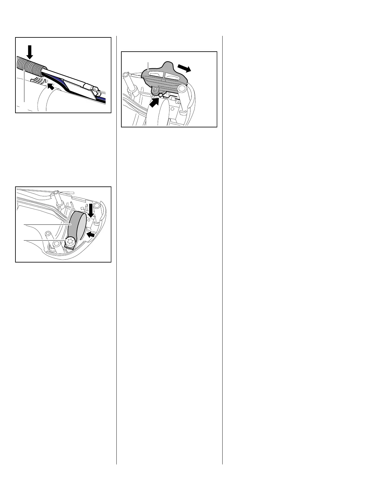
The protective tube (1) must be
properly seated in the convolutions
of the handle molding.
: Push the short circuit and ground
wires in the guide (arrow), then fit
the protective tube (1).
: Place the clamp (1) in its seat
(arrow) and insert the screw (2) –
do not tighten down yet.
– Install the control slide, b 10.1.2
1
9912RA294 TG
1
2
9912RA169 TG
Check operation
: Move the control slide (1) to
"STOP-0", the contact spring
(arrow) must operate the
microswitch in this position – with
an audible click.
– Install the throttle trigger and
lockout lever, b 10.1.1
– Mount the control handle on the
handlebar, b 10.1
– Install throttle cable and short
circuit wire on engine, b 8.2
– Check throttle cable adjustment,
re-adjust if necessary, b 10.2
– Reassemble all other parts in the
reverse sequence.
8.4 Ground Wire
Test and install the ground wire as
described for the short circuit wire.
– Perform contact and continuity
test; replace throttle cable if
necessary, b 8.1, b 8.2, b 8.3
1
9912RA170 TG
 Loading...