8
• The Logger1000 supports various communication manners such as WLAN and 4G.
• The Logger1000 can be connected to various environment sensors, Smart Energy Me-
ters, Meteo Stations, and inverters in the PV power generation system via an RS485 bus.
• Users can access the Web interface via mobile phone or PC, on which parameter config-
uration and remote on-line upgrading can be performed.
• The Logger1000 can transmit data to iSolarCloud and forward background instructions
to downstream devices.
• The Logger1000 is equipped with grid dispatching function, including active power con-
trol, reactive power regulation, etc.
2.4 Product Introduction
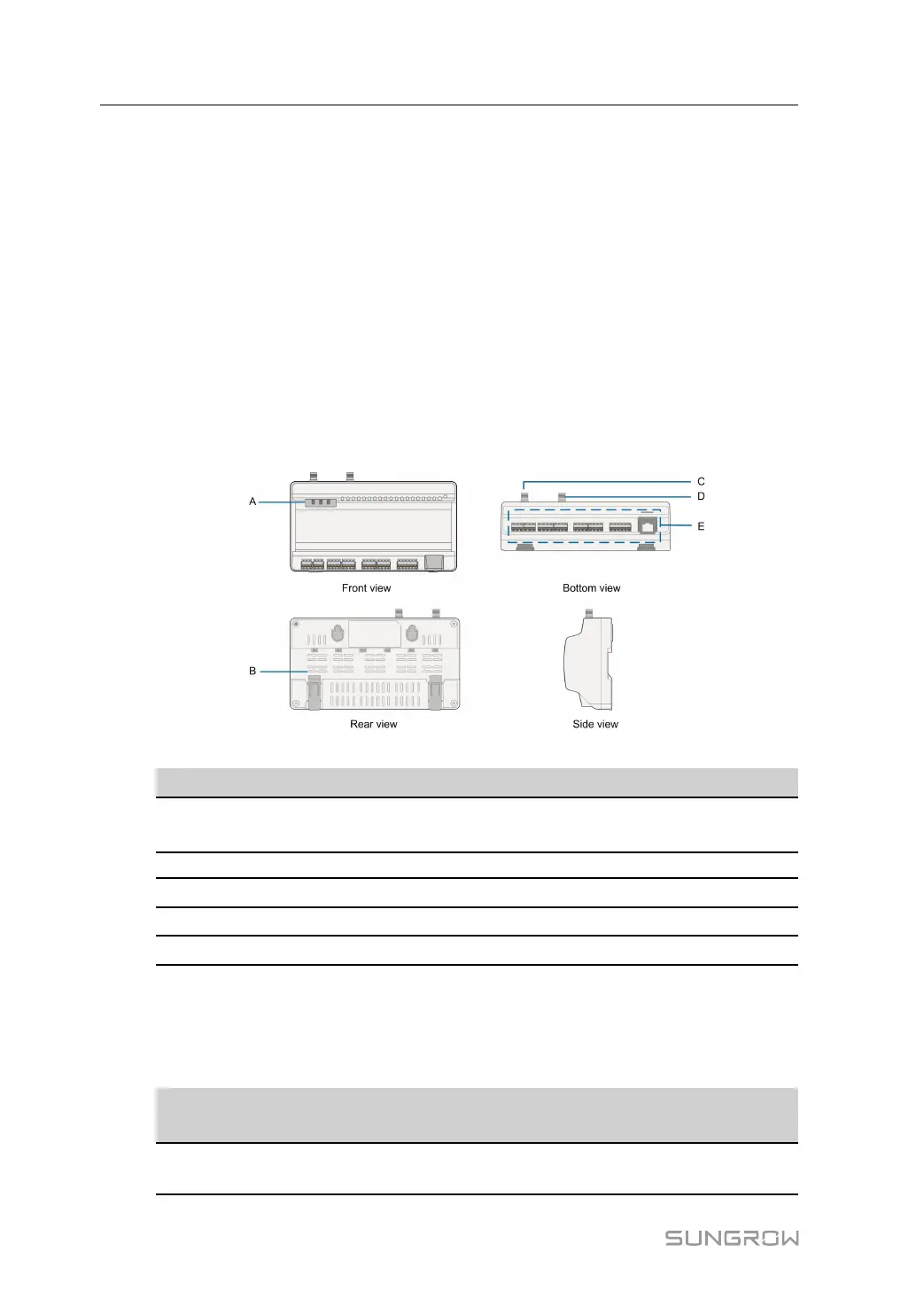
Appearance
figure 2-1 Appearance
Item
Designation Description
A Indicator
Indicate the running state of the
Logger1000
B Vent
-
C
WLAN antenna mounting hole
-
D*
4G antenna mounting hole
-
E
Wiring terminal Refer to "table 5-1 Port description"
Note: D* is 4G antenna mounting hole. The Logger1000A is provided with the hole while the
Logger1000B is not. Specifically, refer to the actual product received. In the following, de-
scription is given by using the Logger1000A as an example.
Indicator
Indicator
(print)
LED color LED status
Description
Running indica-
tor (RUN)
Red/green
Off
No external power supply
connected
2 Product Description User Manual

 Loading...

