27
If multiple inverters are connected to the Logger1000 together with the Meteo Sta-
tion, the Meteo Station should be connected on the very end of the daisy chain.
AI Connection
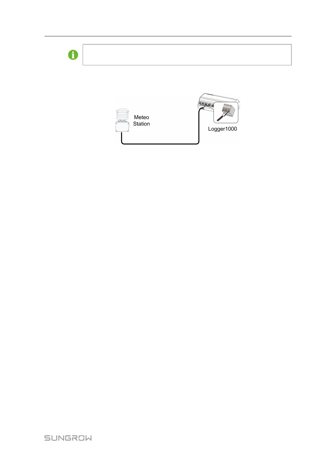
The following figure shows the connection between the Logger1000 and the Meteo Station.
Connect the communication cable led from the Meteo Station to the AI port of the
Logger1000.
5.4 Connection to Background
The Logger1000 can be connected to the background of the PV system via the network port,
and the communication protocol is standard Modbus TCP or IEC104.
As a salve device, the Logger1000 can be accessed by multiple backgrounds and communi-
cate by using the standard protocol. The following figure shows the connection between the
Logger1000 and the background.
The Logger1000 can be connected to multiple monitoring background systems via the
Ethernet switch or router, or it may be connected to the single monitoring background sys-
tem via the network cable.
For example, the Logger1000 is connected to the background system via the Ethernet
switch, and the wiring steps are as follows:
Step 1 Prepare an Ethernet cable of suitable length.
Step 2 Insert one end of the cable into the port of the Ethernet switch and the other end to the "ETH"
port of the Logger1000.
User Manual 5 Electrical Connection

 Loading...

